Toyota CH-R Service Manual: Air Conditioning Panel
Components
COMPONENTS
ILLUSTRATION
|
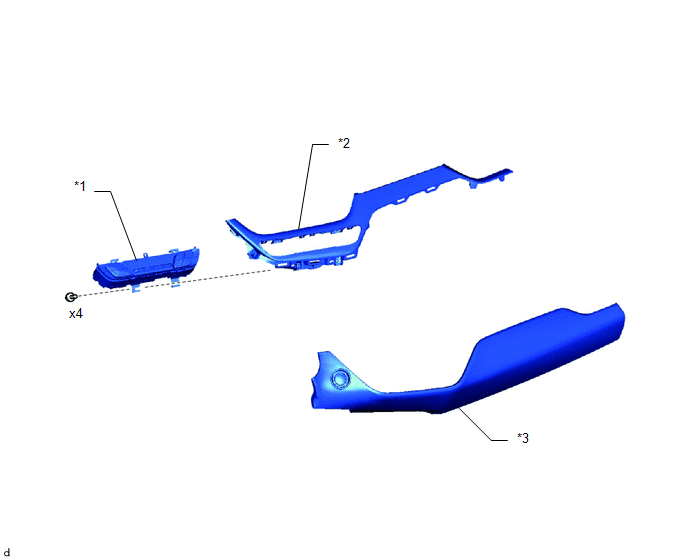
*1 |
AIR CONDITIONING CONTROL ASSEMBLY |
*2 |
INSTRUMENT CLUSTER FINISH LOWER CENTER PANEL SUB-ASSEMBLY |
|
*3 |
INSTRUMENT CLUSTER FINISH PANEL GARNISH ASSEMBLY |
- |
- |
Installation
INSTALLATION
PROCEDURE
1. INSTALL AIR CONDITIONING CONTROL ASSEMBLY
|
(a) Engage the claws to install the air conditioning control assembly. |
|
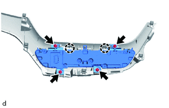
(b) Install the 4 screws.
2. INSTALL INSTRUMENT CLUSTER FINISH LOWER CENTER PANEL SUB-ASSEMBLY
Click here
.gif)
3. INSTALL INSTRUMENT CLUSTER FINISH PANEL GARNISH ASSEMBLY
Click here
Removal
REMOVAL
PROCEDURE
1. REMOVE INSTRUMENT CLUSTER FINISH PANEL GARNISH ASSEMBLY
Click here
.gif)
2. REMOVE INSTRUMENT CLUSTER FINISH LOWER CENTER PANEL SUB-ASSEMBLY
Click here
3. REMOVE AIR CONDITIONING CONTROL ASSEMBLY
|
(a) Remove the 4 screws. |
|
.png)
(b) Disengage the claws to remove the air conditioning control assembly.
 Air Conditioning Filter(for Valeo Made)
Components
COMPONENTS
ILLUSTRATION
*1
AIR FILTER COVER PLATE
*2
CLEAN AIR FILTER
*3
GLOVE COMPARTMENT DOOR ASSEMBLY
...

Other materials:
Toyota CH-R Owners Manual > Air conditioning system: Air conditioning controls
■ Adjusting the temperature setting
Increases the temperature
Decreases the temperature
If the
indicator
is turned off, the system will blow ambient temperature air or heated air.
■ Fan speed setting
Increases the fan speed
Decreases the fan speed
Press
to
turn t ...
Toyota CH-R Service Manual > Rear Disc Brake Pad(for Tmc Made): Installation
INSTALLATION
CAUTION / NOTICE / HINT
NOTICE:
After replacing the rear disc brake pads, the brake pedal may feel soft due to
clearance between the rear disc brake pads and rear disc. Depress the brake pedal
several times until the brake pedal feels firm.
HINT:
The following procedure ...
Toyota C-HR (AX20) 2023-2026 Owner's Manual
Toyota CH-R Owners Manual
- For safety and security
- Instrument cluster
- Operation of each component
- Driving
- Interior features
- Maintenance and care
- When trouble arises
- Vehicle specifications
- For owners
Toyota CH-R Service Manual
- Introduction
- Maintenance
- Audio / Video
- Cellular Communication
- Navigation / Multi Info Display
- Park Assist / Monitoring
- Brake (front)
- Brake (rear)
- Brake Control / Dynamic Control Systems
- Brake System (other)
- Parking Brake
- Axle And Differential
- Drive Shaft / Propeller Shaft
- K114 Cvt
- 3zr-fae Battery / Charging
- Networking
- Power Distribution
- Power Assist Systems
- Steering Column
- Steering Gear / Linkage
- Alignment / Handling Diagnosis
- Front Suspension
- Rear Suspension
- Tire / Wheel
- Tire Pressure Monitoring
- Door / Hatch
- Exterior Panels / Trim
- Horn
- Lighting (ext)
- Mirror (ext)
- Window / Glass
- Wiper / Washer
- Door Lock
- Heating / Air Conditioning
- Interior Panels / Trim
- Lighting (int)
- Meter / Gauge / Display
- Mirror (int)
- Power Outlets (int)
- Pre-collision
- Seat
- Seat Belt
- Supplemental Restraint Systems
- Theft Deterrent / Keyless Entry

0.0065