Toyota CH-R Service Manual: Removal
REMOVAL
CAUTION / NOTICE / HINT
The necessary procedures (adjustment, calibration, initialization, or registration) that must be performed after parts are removed and installed, or replaced during the rear seat outer belt assembly removal/installation are shown below.
Necessary Procedure After Parts Removed/Installed/Replaced|
Replaced Part or Performed Procedure |
Necessary Procedure |
Effect/Inoperative Function when Necessary Procedure not Performed |
Link |
|---|---|---|---|
|
Disconnect cable from negative battery terminal |
Initialize back door lock |
Power door lock control system |
|
|
Memorize steering angle neutral point |
Lane departure alert system (w/ Steering Control) |
|
|
|
Pre-collision system |
CAUTION:
Some of these service operations affect the SRS airbag system. Read the precautionary notices concerning the SRS airbag system before servicing.
Click here .gif)
.png)
HINT:
- Use the same procedure for the RH side and LH side.
- The procedure listed below is for the LH side.
PROCEDURE
1. REMOVE REAR SEAT ASSEMBLY
Click here
2. REMOVE PACKAGE TRAY TRIM PANEL ASSEMBLY (w/ Package Tray Trim)
Click here
3. REMOVE TONNEAU COVER ASSEMBLY (w/ Tonneau Cover)
Click here
4. REMOVE DECK BOARD ASSEMBLY
Click here
5. REMOVE SPARE WHEEL CUSHION
Click here
6. REMOVE DECK FLOOR BOX LH
Click here
7. REMOVE DECK FLOOR BOX RH
Click here
8. REMOVE REAR DOOR SCUFF PLATE (w/o Rear Seat Side Airbag)
Click here
9. REMOVE REAR DOOR SCUFF PLATE (w/ Rear Seat Side Airbag)
Click here
10. REMOVE REAR DOOR OPENING TRIM WEATHERSTRIP
Click here
11. REMOVE REAR SEATBACK HINGE SUB-ASSEMBLY
Click here
12. REMOVE REAR PILLAR COVER (w/ Rear Seat Side Airbag)
Click here
13. REMOVE REAR SEAT SIDE GARNISH (w/o Rear Seat Side Airbag)
Click here
14. REMOVE REAR SEAT SIDE GARNISH (w/ Rear Seat Side Airbag)
Click here
15. REMOVE DECK TRIM REAR COVER
Click here
16. REMOVE NO. 1 LUGGAGE COMPARTMENT LIGHT ASSEMBLY
Click here
17. REMOVE DECK TRIM SIDE PANEL ASSEMBLY
Click here
18. REMOVE ROOF SIDE INNER GARNISH ASSEMBLY
Click here
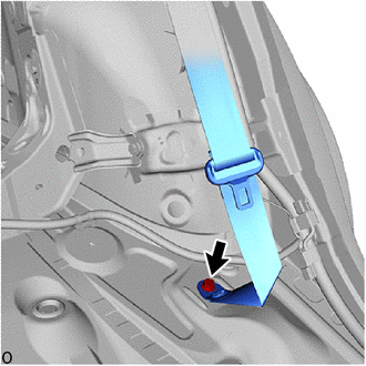
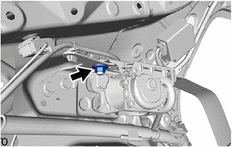
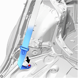
19. REMOVE REAR SEAT 3 POINT TYPE OUTER BELT ASSEMBLY LH (for LH Side)
|
(a) Remove the bolt to disconnect the floor anchor of the rear seat 3 point type outer belt assembly LH. |
|
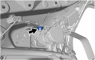
(b) w/o Pretensioner and Force Limiter:
|
(1) Loosen the nut. |
|
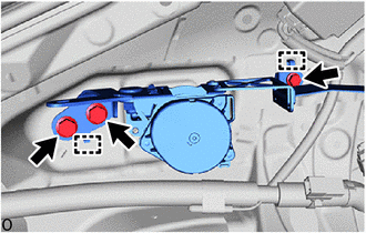
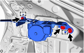
|
(2) Remove the 3 bolts. |
|
(3) Disengage the guides to remove the rear seat 3 point type outer belt assembly LH with bracket.
|
(4) Remove the nut. |
|
(5) Disengage the guides to remove the rear seat 3 point type outer belt assembly LH from the outer belt anchor bracket sub-assembly LH.
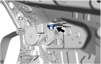
(c) w/ Pretensioner and Force Limiter:
|
(1) Loosen the nut. |
|
|
(2) Remove the 3 bolts. |
|
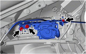
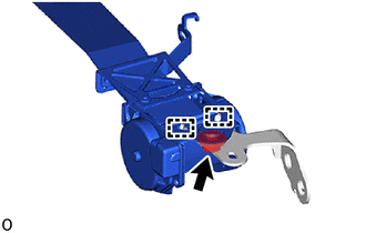
(3) Disengage the guides to separate the rear seat 3 point type outer belt assembly LH with bracket.
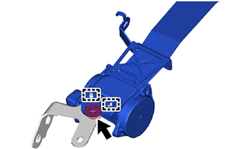
|
(4) Disengage the clamp. |
|
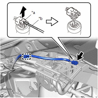
(5) Using a screwdriver with its tip wrapped in protective tape, pull out the locking button to release the lock to disconnect the pretensioner connector as shown in the illustration.
|
(6) Remove the nut. |
|
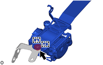
(7) Disengage the guides to remove the rear seat 3 point type outer belt assembly LH from the outer belt anchor bracket sub-assembly LH.
20. REMOVE REAR SEAT 3 POINT TYPE OUTER BELT ASSEMBLY RH (for RH Side)
|
(a) Remove the bolt to disconnect the floor anchor of the rear seat 3 point type outer belt assembly RH. |
|
(b) w/o Pretensioner and Force Limiter:
|
(1) Loosen the nut. |
|
|
(2) Remove the 3 bolts. |
|
(3) Disengage the guides to remove the rear seat 3 point type outer belt assembly RH with bracket.
|
(4) Remove the nut. |
|
(5) Disengage the guides to remove the rear seat 3 point type outer belt assembly RH from the outer belt anchor bracket sub-assembly RH.
(c) w/ Pretensioner and Force Limiter:
|
(1) Disengage the clamp. |
|
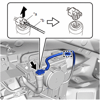
(2) Using a screwdriver with its tip wrapped in protective tape, pull out the locking button to release the lock to disconnect the pretensioner connector as shown in the illustration.
|
(3) Loosen the nut. |
|
|
(4) Remove the 3 bolts. |
|
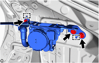
(5) Disengage the guides to remove the rear seat 3 point type outer belt assembly RH with bracket.
|
(6) Remove the nut. |
|
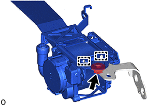
(7) Disengage the guides to remove the rear seat 3 point type outer belt assembly RH from the outer belt anchor bracket sub-assembly RH.
 On-vehicle Inspection
ON-VEHICLE INSPECTION
CAUTION / NOTICE / HINT
CAUTION:
Be sure to correctly follow the removal and installation procedures for the rear
3 point type seat outer belt assembly.
PROCEDURE
1. INSPE ...
 Inspection
INSPECTION
PROCEDURE
1. INSPECT REAR SEAT 3 POINT TYPE OUTER BELT ASSEMBLY
(a) Before installing the rear seat 3 point type outer belt assembly,
check the ELR function.
NOTICE:
...
Other materials:
Toyota CH-R Service Manual > Power Window Control System: All Power Windows do not Operate with Driver Side Door Key Cylinder or Wireless
Transmitter
DESCRIPTION
Wireless Transmitter-linked Function
w/ Smart Key System:
When an electronic key transmitter sub-assembly switch is pushed:
1) the door control receiver receives the wireless door lock signal;
2) the door control receiver sends a signal to the main bod ...
Toyota CH-R Service Manual > Tire Pressure Warning System: Tire Pressure Monitor ECU Communication Stop (C2179/79)
DESCRIPTION
The main body ECU (multiplex network body ECU) sends signals to the tire pressure
warning ECU and receiver via a direct line.
DTC No.
Detection Item
DTC Detection Condition
Trouble Area
Note
C2179/79
T ...
Toyota C-HR (AX20) 2023-2026 Owner's Manual
Toyota CH-R Owners Manual
- For safety and security
- Instrument cluster
- Operation of each component
- Driving
- Interior features
- Maintenance and care
- When trouble arises
- Vehicle specifications
- For owners
Toyota CH-R Service Manual
- Introduction
- Maintenance
- Audio / Video
- Cellular Communication
- Navigation / Multi Info Display
- Park Assist / Monitoring
- Brake (front)
- Brake (rear)
- Brake Control / Dynamic Control Systems
- Brake System (other)
- Parking Brake
- Axle And Differential
- Drive Shaft / Propeller Shaft
- K114 Cvt
- 3zr-fae Battery / Charging
- Networking
- Power Distribution
- Power Assist Systems
- Steering Column
- Steering Gear / Linkage
- Alignment / Handling Diagnosis
- Front Suspension
- Rear Suspension
- Tire / Wheel
- Tire Pressure Monitoring
- Door / Hatch
- Exterior Panels / Trim
- Horn
- Lighting (ext)
- Mirror (ext)
- Window / Glass
- Wiper / Washer
- Door Lock
- Heating / Air Conditioning
- Interior Panels / Trim
- Lighting (int)
- Meter / Gauge / Display
- Mirror (int)
- Power Outlets (int)
- Pre-collision
- Seat
- Seat Belt
- Supplemental Restraint Systems
- Theft Deterrent / Keyless Entry

0.0077