Toyota CH-R Service Manual: Terminals Of Ecu
TERMINALS OF ECU
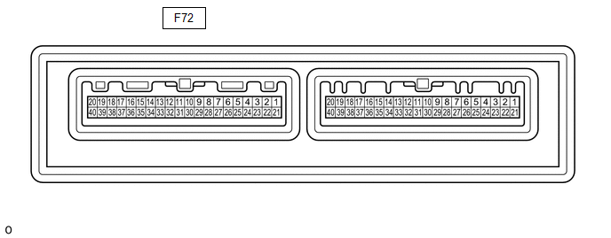
CHECK AIR CONDITIONING AMPLIFIER ASSEMBLY (for TMMT Made)
(a) Disconnect the air conditioning amplifier assembly connector.
(b) Measure the voltage and resistance according to the value(s) in the table below.
|
Tester Connection |
Wiring Color |
Terminal Description |
Condition |
Specified Condition |
|---|---|---|---|---|
|
F72-5 (IG+) - Body ground |
B - Body ground |
IG power supply |
Ignition switch ON |
11 to 14 V |
|
Ignition switch off |
Below 1 V |
|||
|
F72-29 (GND) - Body ground |
W-B - Body ground |
Ground |
Always |
Below 1 Ω |
|
F72-1 (B) - Body ground |
V - Body ground |
Battery power supply |
Always |
11 to 14 V |
(c) Reconnect the air conditioning amplifier assembly connector.
(d) Check for pulse generation according to the value(s) in the table below.
|
Tester Connection |
Wiring Color |
Terminal Description |
Condition |
Specified Condition |
|---|---|---|---|---|
|
F72-3 (LIN1) - Body ground |
L - Body ground |
Seat heater switch signal |
Ignition switch ON |
Pulse generation |
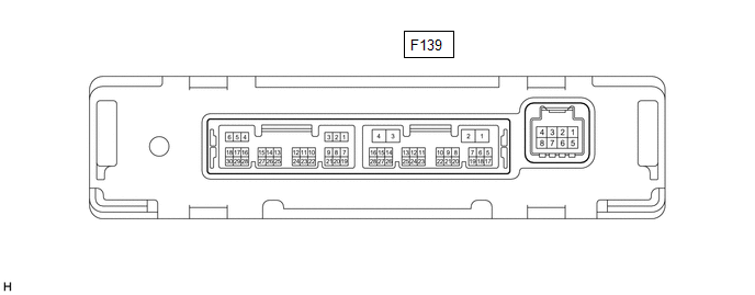
CHECK AIR CONDITIONING AMPLIFIER ASSEMBLY (for TMC Made)
(a) Disconnect the air conditioning amplifier assembly connector.
(b) Measure the voltage and resistance according to the value(s) in the table below.
|
Tester Connection |
Wiring Color |
Terminal Description |
Condition |
Specified Condition |
|---|---|---|---|---|
|
F139-2 (IG+) - Body ground |
B - Body ground |
IG power supply |
Ignition switch ON |
11 to 14 V |
|
Ignition switch off |
Below 1 V |
|||
|
F139-4 (GND) - Body ground |
W-B - Body ground |
Ground |
Always |
Below 1 Ω |
|
F139-1 (B) - Body ground |
V - Body ground |
Battery power supply |
Always |
11 to 14 V |
(c) Reconnect the air conditioning amplifier assembly connector.
(d) Check for pulse generation according to the value(s) in the table below.
|
Tester Connection |
Wiring Color |
Terminal Description |
Condition |
Specified Condition |
|---|---|---|---|---|
|
F139-14 (LIN1) - Body ground |
BE - Body ground |
Seat heater switch signal |
Ignition switch ON |
Pulse generation |
CHECK AIR CONDITIONING CONTROL ASSEMBLY

(a) Disconnect the air conditioning control assembly connector.
(b) Measure the voltage and resistance according to the value(s) in the table below.
|
Tester Connection |
Wiring Color |
Terminal Description |
Condition |
Specified Condition |
|---|---|---|---|---|
|
F61-16 (GND) - Body ground |
W-B - Body ground |
Ground |
Always |
Below 1 Ω |
|
F61-10 (IG+) - F61-16 (GND) |
BE - W-B |
IG power supply |
Ignition switch ON |
11 to 14 V |
|
Ignition switch off |
Below 1 V |
(c) Reconnect the air conditioning control assembly connector.
(d) Measure the voltage according to the value(s) in the table below.
(e) Check for pulse generation according to the value(s) in the table below.
|
Tester Connection |
Wiring Color |
Terminal Description |
Condition |
Specified Condition |
|---|---|---|---|---|
|
F61-2 (LIN1) - F61-16 (GND) |
L - W-B |
Seat heater switch signal |
Ignition switch ON |
Pulse generation |
|
F61-4 (RV) - F61-16 (GND) |
SB - W-B |
Seat heater switch volume signal |
Ignition switch ON, seat heater switch (for front passenger side) off |
Below 0.6 V |
|
Ignition switch ON, seat heater switch (for front passenger side) HI |
3.9 to 5.5 V |
|||
|
Ignition switch ON, seat heater switch (for front passenger side) MID |
3.4 to 4.7 V |
|||
|
Ignition switch ON, seat heater switch (for front passenger side) LO |
2.5 to 3.5 V |
|||
|
F61-11 (SW) - F61-16 (GND) |
R - W-B |
Seat heater switch volume signal |
Ignition switch ON, seat heater switch (for front passenger side) off |
Below 1 V |
|
Ignition switch ON, seat heater switch (for front passenger side) on |
11 to 14 V |
|||
|
F61-6 (RV) - F61-16 (GND) |
LG - W-B |
Seat heater switch volume signal |
Ignition switch ON, seat heater switch (for driver side) off |
Below 0.6 V |
|
Ignition switch ON, seat heater switch (for driver side) HI |
3.9 to 5.5 V |
|||
|
Ignition switch ON, seat heater switch (for driver side) MID |
3.4 to 4.7 V |
|||
|
Ignition switch ON, seat heater switch (for driver side) LO |
2.5 to 3.5 V |
|||
|
F61-12 (SW) - F61-16 (GND) |
P - W-B |
Seat heater switch volume signal |
Ignition switch ON, seat heater switch (for driver side) off |
Below 1 V |
|
Ignition switch ON, seat heater switch (for driver side) on |
11 to 14 V |
 Problem Symptoms Table
PROBLEM SYMPTOMS TABLE
NOTICE:
If the battery voltage is low, the seat heater system may not operate. Refer
to Data List for power steering system.
Click here
HINT:
Use the table belo ...
 Diagnosis System
DIAGNOSIS SYSTEM
DESCRIPTION
(a) Seat heater system data and Diagnostic Trouble Codes (DTCs) can be read through
the Data Link Connector 3 (DLC3) of the vehicle. When the system seems to be malfun ...
Other materials:
Toyota CH-R Service Manual > Airbag System: Short in Rear Pretensioner Squib RH Circuit (B1920/77-B1923/77)
DESCRIPTION
The rear pretensioner squib RH circuit consists of the airbag sensor assembly
and rear seat 3 point type outer belt assembly RH.
The airbag sensor assembly uses this circuit to deploy the pretensioner when
deployment conditions are met.
These DTCs are stored when a malfunction is ...
Toyota CH-R Owners Manual > Tire information: Uniform Tire Quality Grading
This information has been prepared in accordance with regulations issued by the
National Highway Traffic Safety Administration of the U.S. Department of Transportation.
It provides the purchasers and/or prospective purchasers of Toyota vehicles with
information on uniform tire quality grading.
...
Toyota C-HR (AX20) 2023-2026 Owner's Manual
Toyota CH-R Owners Manual
- For safety and security
- Instrument cluster
- Operation of each component
- Driving
- Interior features
- Maintenance and care
- When trouble arises
- Vehicle specifications
- For owners
Toyota CH-R Service Manual
- Introduction
- Maintenance
- Audio / Video
- Cellular Communication
- Navigation / Multi Info Display
- Park Assist / Monitoring
- Brake (front)
- Brake (rear)
- Brake Control / Dynamic Control Systems
- Brake System (other)
- Parking Brake
- Axle And Differential
- Drive Shaft / Propeller Shaft
- K114 Cvt
- 3zr-fae Battery / Charging
- Networking
- Power Distribution
- Power Assist Systems
- Steering Column
- Steering Gear / Linkage
- Alignment / Handling Diagnosis
- Front Suspension
- Rear Suspension
- Tire / Wheel
- Tire Pressure Monitoring
- Door / Hatch
- Exterior Panels / Trim
- Horn
- Lighting (ext)
- Mirror (ext)
- Window / Glass
- Wiper / Washer
- Door Lock
- Heating / Air Conditioning
- Interior Panels / Trim
- Lighting (int)
- Meter / Gauge / Display
- Mirror (int)
- Power Outlets (int)
- Pre-collision
- Seat
- Seat Belt
- Supplemental Restraint Systems
- Theft Deterrent / Keyless Entry

0.0086