Toyota CH-R Service Manual: Removal
REMOVAL
CAUTION / NOTICE / HINT
The necessary procedures (adjustment, calibration, initialization, or registration) that must be performed after parts are removed, installed, or replaced during the front lumbar power seat switch removal/installation are shown below.
Necessary Procedure After Parts Removed/Installed/Replaced|
Replacement Part or Procedure |
Necessary Procedures |
Effects / Inoperative when not performed |
Link |
|---|---|---|---|
|
Disconnect cable from negative battery terminal |
Initialize back door lock |
Power door lock control system |
|
|
Memorize steering angle neutral point |
Lane departure alert system (w/ Steering Control) |
|
|
|
Pre-collision system |
CAUTION:
- Be sure to read Precaution thoroughly before servicing.
Click here
.gif)
.png)
- Wear protective gloves. Sharp areas on the parts may injure your hands.
HINT:
Front lumbar power seat switch is available only on the driver side.
PROCEDURE
1. REMOVE FRONT SEAT ASSEMBLY
Click here
2. DISCONNECT SEPARATE TYPE FRONT SEATBACK COVER
Click here
3. REMOVE VERTICAL ADJUSTING HANDLE
Click here
4. REMOVE RECLINING HINGE OUTER COVER
Click here
5. REMOVE RECLINING ADJUSTER RELEASE HANDLE
Click here
6. REMOVE SEAT ADJUSTER COVER CAP
Click here
7. REMOVE FRONT SEAT CUSHION SHIELD
Click here
8. REMOVE FRONT LUMBAR POWER SEAT SWITCH
|
(a) Remove the 2 screws. |
|
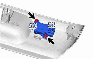
(b) Disengage the guides to remove the front lumber power seat switch.
 Inspection
INSPECTION
PROCEDURE
1. INSPECT FRONT LUMBAR POWER SEAT SWITCH
(a) Check the resistance.
(1) Measure the resistance according to the value(s) in the table below.
Standard Resistance: ...
 Installation
INSTALLATION
CAUTION / NOTICE / HINT
CAUTION:
Be sure to read Precaution thoroughly before servicing.
Click here
Wear protective gloves. Sharp areas on the parts may inj ...
Other materials:
Toyota CH-R Service Manual > Rear Seat Inner Belt Assembly(for Lh Side): Inspection
INSPECTION
PROCEDURE
1. INSPECT REAR SEAT INNER WITH CENTER BELT ASSEMBLY LH (w/ Seat Belt Warning
System)
(a) for LH:
(1) Check the resistance.
Measure the resistance according to the value(s) in the table below.
Standard Resistance:
Tester Connection
...
Toyota CH-R Service Manual > Tire Pressure Warning System: Transmitter ID1 Error (C2141/41-C2145/45)
DESCRIPTION
The tire pressure warning valve and transmitters that are installed in the tire
and wheel assemblies measure the tire pressures. The measured values are transmitted
to the tire pressure warning ECU and receiver in the vehicle as radio waves. The
ECU compares the measured tire pres ...
Toyota C-HR (AX20) 2023-2026 Owner's Manual
Toyota CH-R Owners Manual
- For safety and security
- Instrument cluster
- Operation of each component
- Driving
- Interior features
- Maintenance and care
- When trouble arises
- Vehicle specifications
- For owners
Toyota CH-R Service Manual
- Introduction
- Maintenance
- Audio / Video
- Cellular Communication
- Navigation / Multi Info Display
- Park Assist / Monitoring
- Brake (front)
- Brake (rear)
- Brake Control / Dynamic Control Systems
- Brake System (other)
- Parking Brake
- Axle And Differential
- Drive Shaft / Propeller Shaft
- K114 Cvt
- 3zr-fae Battery / Charging
- Networking
- Power Distribution
- Power Assist Systems
- Steering Column
- Steering Gear / Linkage
- Alignment / Handling Diagnosis
- Front Suspension
- Rear Suspension
- Tire / Wheel
- Tire Pressure Monitoring
- Door / Hatch
- Exterior Panels / Trim
- Horn
- Lighting (ext)
- Mirror (ext)
- Window / Glass
- Wiper / Washer
- Door Lock
- Heating / Air Conditioning
- Interior Panels / Trim
- Lighting (int)
- Meter / Gauge / Display
- Mirror (int)
- Power Outlets (int)
- Pre-collision
- Seat
- Seat Belt
- Supplemental Restraint Systems
- Theft Deterrent / Keyless Entry

0.0108