Toyota CH-R Service Manual: Lost Communication with Front Panel LIN (B14B2)
DESCRIPTION
The air conditioning control assembly communicates with the air conditioning amplifier assembly via LIN communication.
If the LIN communication system malfunctions, the air conditioning amplifier assembly does not operate even if the air conditioning control assembly is operated.
|
DTC No. |
Detection Item |
DTC Detection Condition |
Trouble Area |
Memory |
|---|---|---|---|---|
|
B14B2 |
Lost Communication with Front Panel LIN |
Lost communication with air conditioning control assembly |
|
Memorized (10 seconds or more)* |
- *: The air conditioning amplifier assembly stores this DTC if the malfunction has occurred for the period of time indicated in the brackets.
WIRING DIAGRAM

CAUTION / NOTICE / HINT
NOTICE:
Inspect the fuses for circuits related to this system before performing the following procedure.
PROCEDURE
|
1. |
CHECK HARNESS AND CONNECTOR (AIR CONDITIONING CONTROL ASSEMBLY - POWER SOURCE) |
|
(a) Disconnect the air conditioning control assembly connector. |
|

(b) Measure the voltage according to the value(s) in the table below.
Standard Voltage:
|
Tester Connection |
Switch Condition |
Specified Condition |
|---|---|---|
|
F61-10 (IG+) - Body ground |
Ignition switch ON |
11 to 14 V |
|
F61-10 (IG+) - Body ground |
Ignition switch off |
Below 1 V |
(c) Measure the resistance according to the value(s) in the table below.
Standard Resistance:
|
Tester Connection |
Switch Condition |
Specified Condition |
|---|---|---|
|
F61-16 (GND) -Body ground |
Always |
Below 1 Ω |
| NG | .gif) |
REPAIR OR REPLACE HARNESS OR CONNECTOR (POWER SOURCE CIRCUIT) |
|

|
2. |
CHECK HARNESS AND CONNECTOR (AIR CONDITIONING AMPLIFIER ASSEMBLY - AIR CONDITIONING CONTROL ASSEMBLY) |
(a) Disconnect the F72 air conditioning amplifier assembly connector.
(b) Measure the resistance according to the value(s) in the table below.
Standard Resistance:
|
Tester Connection |
Condition |
Specified Condition |
|---|---|---|
|
F61-2 (LIN1) - F72-3 (LIN1) |
Always |
Below 1 Ω |
|
F61-2 (LIN1) or F72-3 (LIN1) - Body ground |
Always |
10 kΩ or higher |
| NG | |
REPAIR OR REPLACE HARNESS OR CONNECTOR |
|
|
3. |
INSPECT AIR CONDITIONING AMPLIFIER ASSEMBLY |
(a) Reconnect the F72 air conditioning amplifier assembly connector.
(b) Turn the ignition switch ON.
(c) Connect an oscilloscope to terminals F72-3 (LIN1) and F72-29 (GND) of the air conditioning amplifier assembly and check the waveform.
OK:
Waveform is similar to that shown in the illustration.
|
Item |
Content |
|---|---|
|
Tool Setting |
2 V/DIV., 20 ms./DIV. |
|
Vehicle Condition |
Ignition switch ON |

|
*a |
Component with harness connected (Air Conditioning Amplifier Assembly) |
- |
- |
| NG | |
REPLACE AIR CONDITIONING AMPLIFIER ASSEMBLY |
|
|
4. |
INSPECT AIR CONDITIONING CONTROL ASSEMBLY |
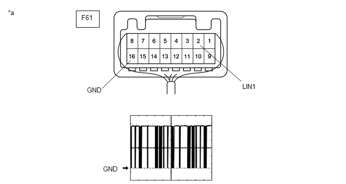
(a) Reconnect the F61 air conditioning control assembly connector.
(b) Turn the ignition switch ON.
(c) Connect an oscilloscope to terminals F61-2 (LIN1) and F61-16 (GND) of the air conditioning control assembly and check the waveform.
OK:
Waveform is similar to that shown in the illustration.
|
Item |
Content |
|---|---|
|
Tool Setting |
2 V/DIV., 20 ms./DIV. |
|
Vehicle Condition |
Ignition switch ON |
|
*a |
Component with harness connected (Air Conditioning Control Assembly) |
- |
- |
| OK | |
REPLACE AIR CONDITIONING AMPLIFIER ASSEMBLY |
| NG | |
REPLACE AIR CONDITIONING CONTROL ASSEMBLY |
 Lost Communication with ECM (U0100-U0142,U0155)
DESCRIPTION
DTC No.
Detection Item
DTC Detection Condition
Trouble Area
Memory
U0100
Lost Communication with ECM
...
 Compressor Solenoid Circuit (B1451)
DESCRIPTION
In this circuit, the compressor with pulley assembly (compressor solenoid) receives
a refrigerant compression demand signal from the air conditioning amplifier assembly.
Based on this ...
Other materials:
Toyota CH-R Service Manual > Window Defogger System: System Description
SYSTEM DESCRIPTION
GENERAL
(a) The rear window defogger wire is attached to the inside of the rear window
and defogs the window surface quickly when the rear window defogger switch is pressed.
The indicator light on the switch illuminates while the system is operating. This
system automatica ...
Toyota CH-R Service Manual > Outer Rear View Mirror: Reassembly
REASSEMBLY
CAUTION / NOTICE / HINT
HINT:
Use the same procedure for the RH side and LH side.
The following procedure is for the LH side.
PROCEDURE
1. INSTALL NO. 2 OUTER MIRROR COVER (w/ Illumination)
(a) Engage the claws to install the No. 2 outer mirror cover as shown in th ...
Toyota C-HR (AX20) 2023-2026 Owner's Manual
Toyota CH-R Owners Manual
- For safety and security
- Instrument cluster
- Operation of each component
- Driving
- Interior features
- Maintenance and care
- When trouble arises
- Vehicle specifications
- For owners
Toyota CH-R Service Manual
- Introduction
- Maintenance
- Audio / Video
- Cellular Communication
- Navigation / Multi Info Display
- Park Assist / Monitoring
- Brake (front)
- Brake (rear)
- Brake Control / Dynamic Control Systems
- Brake System (other)
- Parking Brake
- Axle And Differential
- Drive Shaft / Propeller Shaft
- K114 Cvt
- 3zr-fae Battery / Charging
- Networking
- Power Distribution
- Power Assist Systems
- Steering Column
- Steering Gear / Linkage
- Alignment / Handling Diagnosis
- Front Suspension
- Rear Suspension
- Tire / Wheel
- Tire Pressure Monitoring
- Door / Hatch
- Exterior Panels / Trim
- Horn
- Lighting (ext)
- Mirror (ext)
- Window / Glass
- Wiper / Washer
- Door Lock
- Heating / Air Conditioning
- Interior Panels / Trim
- Lighting (int)
- Meter / Gauge / Display
- Mirror (int)
- Power Outlets (int)
- Pre-collision
- Seat
- Seat Belt
- Supplemental Restraint Systems
- Theft Deterrent / Keyless Entry

0.008