Toyota CH-R Service Manual: Compressor Solenoid Circuit (B1451)
DESCRIPTION
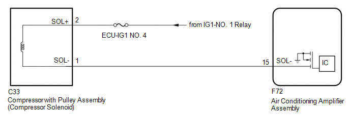
In this circuit, the compressor with pulley assembly (compressor solenoid) receives a refrigerant compression demand signal from the air conditioning amplifier assembly.
Based on this signal, the compressor with pulley assembly (compressor solenoid) changes the amount of compressor output.
|
DTC No. |
Detection Item |
DTC Detection Condition |
Trouble Area |
Memory |
|---|---|---|---|---|
|
B1451 |
Compressor Solenoid Circuit |
Any of the following conditions is met:
|
|
- |
|
Vehicle Condition |
|||
|---|---|---|---|
|
Pattern 1 |
Pattern 2 |
||
|
Diagnosis Condition |
Ignition switch ON |
○ |
○ |
|
Malfunction Status |
Open in compressor solenoid circuit |
○ |
- |
|
Short in compressor solenoid circuit |
- |
○ |
|
|
Detection Time |
30 seconds or more |
30 seconds or more |
|
|
Number of Trips |
1 trip |
1 trip |
|
HINT:
DTC will be output when conditions for either of the patterns in the table above are met.
WIRING DIAGRAM
CAUTION / NOTICE / HINT
NOTICE:
Inspect the fuses for circuits related to this system before performing the following procedure.
PROCEDURE
|
1. |
INSPECT COMPRESSOR WITH PULLEY ASSEMBLY (COMPRESSOR SOLENOID) |
(a) Remove the compressor with pulley assembly (compressor solenoid).
Click here
.gif)
(b) Inspect the compressor with pulley assembly (compressor solenoid).
Click here
| NG | .gif) |
REPLACE COMPRESSOR WITH PULLEY ASSEMBLY (COMPRESSOR SOLENOID) |
|
.gif)
|
2. |
CHECK HARNESS AND CONNECTOR (COMPRESSOR WITH PULLEY ASSEMBLY (COMPRESSOR SOLENOID) - POWER SOURCE) |
(a) Measure the resistance according to the value(s) in the table below.
Standard Voltage:
|
Tester Connection |
Switch Condition |
Specified Condition |
|---|---|---|
|
C33-2 (SOL+) - Body ground |
Ignition switch ON |
11 to 14 V |
| NG | |
REPAIR OR REPLACE HARNESS OR CONNECTOR |
|
|
3. |
CHECK HARNESS AND CONNECTOR (COMPRESSOR WITH PULLEY ASSEMBLY (COMPRESSOR SOLENOID) - AIR CONDITIONING AMPLIFIER ASSEMBLY) |
(a) Disconnect the F72 air conditioning amplifier assembly connector.
(b) Measure the resistance according to the value(s) in the table below.
Standard Resistance:
|
Tester Connection |
Condition |
Specified Condition |
|---|---|---|
|
C33-1 (SOL-) - F72-15 (SOL-) |
Always |
Below 1 Ω |
|
C33-1 (SOL-) or F72-15 (SOL-) - Body ground |
Always |
10 kΩ or higher |
|
Result |
Proceed to |
|---|---|
|
NG |
A |
|
OK (When troubleshooting according to the Problem Symptoms Table) |
B |
|
OK (When troubleshooting according to the DTC) |
C |
| A | |
REPAIR OR REPLACE HARNESS OR CONNECTOR |
| B | |
PROCEED TO NEXT SUSPECTED AREA SHOWN IN PROBLEM SYMPTOMS TABLE |
|
|
4. |
CHECK FOR DTC |
(a) Clear the DTCs.
Click here
(b) Check for DTCs.
Click here
|
Result |
Proceed to |
|---|---|
|
DTCs are not output |
A |
|
DTCs are output |
B |
| A | |
USE SIMULATION METHOD TO CHECK |
| B | |
REPLACE AIR CONDITIONING AMPLIFIER ASSEMBLY |
 Lost Communication with Front Panel LIN (B14B2)
DESCRIPTION
The air conditioning control assembly communicates with the air conditioning
amplifier assembly via LIN communication.
If the LIN communication system malfunctions, the air conditionin ...
 Pressure Sensor Circuit (B1423)
DESCRIPTION
This DTC is stored if refrigerant pressure on the high pressure side is extremely
low (176 kPa (1.8 kgf/cm2, 26 psi) or less)*1, (195 kPa (2.0 kgf/cm2, 28 psi) or
less)*2 or extremely ...
Other materials:
Toyota CH-R Service Manual > Air Conditioning System(for Automatic Air Conditioning System With Side-mounted
Air Conditioner Pressure Sensor): How To Proceed With Troubleshooting
CAUTION / NOTICE / HINT
HINT:
Use the following procedure to troubleshoot the air conditioning system.
*: Use the Techstream.
PROCEDURE
1.
VEHICLE BROUGHT TO WORKSHOP
NEXT
...
Toyota CH-R Service Manual > Wireless Door Lock Control System(w/ Smart Key System): How To Proceed With Troubleshooting
CAUTION / NOTICE / HINT
HINT:
The wireless door lock control system troubleshooting procedure is based
on the premise that the power door lock control system is operating properly.
Check the power door lock control system first before troubleshooting the
wireless door lock cont ...
Toyota C-HR (AX20) 2023-2026 Owner's Manual
Toyota CH-R Owners Manual
- For safety and security
- Instrument cluster
- Operation of each component
- Driving
- Interior features
- Maintenance and care
- When trouble arises
- Vehicle specifications
- For owners
Toyota CH-R Service Manual
- Introduction
- Maintenance
- Audio / Video
- Cellular Communication
- Navigation / Multi Info Display
- Park Assist / Monitoring
- Brake (front)
- Brake (rear)
- Brake Control / Dynamic Control Systems
- Brake System (other)
- Parking Brake
- Axle And Differential
- Drive Shaft / Propeller Shaft
- K114 Cvt
- 3zr-fae Battery / Charging
- Networking
- Power Distribution
- Power Assist Systems
- Steering Column
- Steering Gear / Linkage
- Alignment / Handling Diagnosis
- Front Suspension
- Rear Suspension
- Tire / Wheel
- Tire Pressure Monitoring
- Door / Hatch
- Exterior Panels / Trim
- Horn
- Lighting (ext)
- Mirror (ext)
- Window / Glass
- Wiper / Washer
- Door Lock
- Heating / Air Conditioning
- Interior Panels / Trim
- Lighting (int)
- Meter / Gauge / Display
- Mirror (int)
- Power Outlets (int)
- Pre-collision
- Seat
- Seat Belt
- Supplemental Restraint Systems
- Theft Deterrent / Keyless Entry

0.0092