Toyota CH-R Service Manual: Pressure Sensor Circuit (B1423)
DESCRIPTION
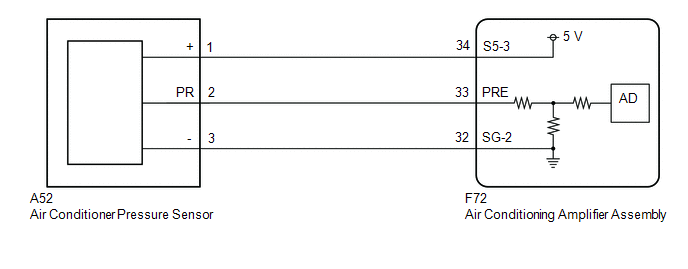
This DTC is stored if refrigerant pressure on the high pressure side is extremely low (176 kPa (1.8 kgf/cm2, 26 psi) or less)*1, (195 kPa (2.0 kgf/cm2, 28 psi) or less)*2 or extremely high (3025 kPa (30.8 kgf/cm2, 439 psi) or more)*1, (2812 kPa (28.7 kgf/cm2, 408 psi) or more)*2. The air conditioner pressure sensor, which is installed to the high pressure side pipe to detect refrigerant pressure, sends a refrigerant pressure signal to the air conditioning amplifier assembly. The air conditioning amplifier assembly converts this signal to a pressure value according to the sensor characteristics and uses it to control the compressor.
- *1: for HFC-134a (R134a)
- *2: for HFO-1234yf (R1234yf)
|
DTC No. |
Detection Item |
DTC Detection Condition |
Trouble Area |
Memory |
|---|---|---|---|---|
|
B1423 |
Pressure Sensor Circuit |
Any of the following conditions is met:
|
|
- |
|
Vehicle Condition |
|||||
|---|---|---|---|---|---|
|
Pattern 1 |
Pattern 2 |
Pattern 3 |
Pattern 4 |
||
|
Diagnosis Condition |
Ignition switch ON |
○ |
○ |
○ |
○ |
|
Only when the outside temperature is 5°C (41°F) or more. |
○ |
○ |
○ |
○ |
|
|
Malfunction Status |
Open in air conditioner pressure sensor circuit |
○ |
- |
- |
- |
|
Short in air conditioner pressure sensor circuit |
- |
○ |
- |
- |
|
|
for HFC-134a (R134a): Refrigerant pressure on high pressure side is extremely low (176 kPa (1.8 kgf/cm2, 26 psi) |
- |
- |
○ |
- |
|
|
for HFO-1234yf (R1234yf): Refrigerant pressure on high pressure side is extremely low (195 kPa (2.0 kgf/cm2, 28 psi) or less) |
- |
- |
○ |
- |
|
|
for HFC-134a (R134a): Refrigerant pressure on high pressure side is extremely high (3025 kPa (30.8 kgf/cm2, 439 psi) or more) |
- |
- |
○ |
○ |
|
|
for HFO-1234yf (R1234yf): Refrigerant pressure on high pressure side is extremely high (2812 kPa (28.7 kgf/cm2, 408 psi) or more) |
- |
- |
- |
○ |
|
|
Detection Time |
4 seconds or more |
4 seconds or more |
4 seconds or more |
4 seconds or more |
|
|
Number of Trips |
1 trip |
1 trip |
1 trip |
1 trip |
|
HINT:
DTC will be output when conditions for either of the patterns in the table above are met.
WIRING DIAGRAM
PROCEDURE
|
1. |
CHECK HARNESS AND CONNECTOR (POWER SOURCE CIRCUIT) |
|
(a) Disconnect the air conditioner pressure sensor connector. |
|
.png)
(b) Measure the voltage according to the value(s) in the table below.
Standard Voltage:
|
Tester Connection |
Switch Condition |
Specified Condition |
|---|---|---|
|
A52-1 (+) - A52-3 (-) |
Ignition switch ON |
4.75 to 5.25 V |
| NG | .gif) |
GO TO STEP 16 |
|
.gif)
|
2. |
INSPECT AIR CONDITIONER PRESSURE SENSOR (SENSOR SIGNAL CIRCUIT) |
(a) Reconnect the A52 air conditioner pressure sensor connector.
(b) Remove the air conditioning amplifier assembly with the connectors still connected.
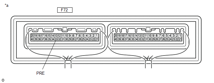
(c) Measure the voltage according to the value(s) in the table below.
|
*a |
Component with harness connected (Air Conditioning Amplifier Assembly) |
- |
- |
Standard Voltage:
|
Tester Connection |
Switch Condition |
Specified Condition |
|---|---|---|
|
F72-33 (PRE) - Body ground |
Ignition switch ON (A/C switch: off) |
0.74 to 4.61 V |
HINT:
If the result is not as specified, there may be a malfunction in the air conditioning amplifier assembly, air conditioner pressure sensor, or wire harness. It is also possible that the amount of refrigerant may not be appropriate.
| NG | |
GO TO STEP 10 |
|
|
3. |
INSPECT AIR CONDITIONER PRESSURE SENSOR (SENSOR SIGNAL CIRCUIT) |
(a) Measure the voltage when the following conditions are met.
Measurement Condition:|
Item |
Condition |
|---|---|
|
Vehicle doors |
Fully open |
|
Temperature setting |
MAX COLD |
|
Blower speed |
HI |
|
A/C switch |
On |
|
Recirculation/fresh switch |
RECIRCULATION |
|
Interior temperature |
25 to 35°C (77 to 95°F) |
|
Engine speed |
2000 rpm |
NOTICE:
- If refrigerant pressure on the high pressure side becomes extremely high during the inspection (if the voltage exceeds 4.61 V), the fail-safe function stops compressor operation. Therefore, measure the voltage before the fail-safe operation.
- It is necessary to measure the voltage for a certain amount of time (approximately 10 minutes) because the malfunction may recur after a while.
HINT:
When the outside air temperature is low (below -1.5°C (29.3°F)), the compressor stops due to operation of the cooler (ambient temp. sensor) thermistor and the No. 1 cooler thermistor (evaporator temperature sensor) to prevent the evaporator from freezing. In this case, perform the inspection in a warm indoor environment.
(1) Measure the voltage according to the value(s) in the table below.

|
*a |
Component with harness connected (Air Conditioning Amplifier Assembly) |
- |
- |
Standard Voltage:
|
Tester Connection |
Switch Condition |
Specified Condition |
|---|---|---|
|
F72-33 (PRE) - Body ground |
Ignition switch ON (A/C switch: On) |
0.74 to 4.61 V |
|
Result |
Proceed to |
|---|---|
|
OK (When troubleshooting according to DTC) |
A |
|
OK (When troubleshooting according to Problem Symptoms Table) |
B |
|
NG |
C |
| A | |
REPLACE AIR CONDITIONING AMPLIFIER ASSEMBLY |
| B | |
PROCEED TO NEXT SUSPECTED AREA SHOWN IN PROBLEM SYMPTOMS TABLE |
|
|
4. |
INSPECT COOLING FAN SYSTEM |
(a) Check if the cooling fan operates normally.
Click here
.gif)
|
Result |
Proceed to |
|---|---|
|
OK |
A |
|
NG |
B |
| B | |
GO TO COOLING FAN SYSTEM |
|
|
5. |
CHARGE SYSTEM WITH REFRIGERANT |
(a) Use a refrigerant recovery unit to recover refrigerant.
(b) Evacuate the air conditioning system.
(c) Add an appropriate amount of refrigerant.
- for HFC-134a (R134a): Click here
- for HFO-1234yf (R1234yf): Click here
HINT:
If refrigerant is added and the system has not been properly evacuated (insufficient vacuum time), moisture in the air remaining in the system will freeze in the cooler expansion valve, blocking the flow on the high pressure side. Therefore, in order to confirm the problem, recover the refrigerant and properly evacuate the system. Add an appropriate amount of refrigerant, and check for the DTC.
|
|
6. |
RECHECK FOR DTC |
(a) Recheck for the DTC when the following conditions are met.
Measurement Condition:|
Item |
Condition |
|---|---|
|
Vehicle doors |
Fully open |
|
Temperature setting |
MAX COLD |
|
Blower speed |
HI |
|
A/C switch |
On |
|
Recirculation/fresh switch |
RECIRCULATION |
|
Interior temperature |
25 to 35°C (77 to 95°F) |
|
Engine speed |
2000 rpm |
NOTICE:
If refrigerant pressure on the high pressure side becomes high, the DTC will be stored. It is necessary to operate the air conditioning system for a certain amount of time (approximately 10 minutes) because the DTC may be stored after the air conditioning operates for a while.
HINT:
- When the outside air temperature is low (below -1.5°C (29.3°F)), the compressor stops due to operation of the cooler (ambient temp. sensor) thermistor and the No. 1 cooler thermistor (evaporator temperature sensor) to prevent the evaporator from freezing. In this case, perform the inspection in a warm indoor environment.
- If refrigerant is added and the system has not been properly evacuated (insufficient vacuum time), moisture in the air remaining in the system will freeze in the cooler expansion valve, blocking the flow on the high pressure side. Therefore, in order to confirm the problem, recover the refrigerant and properly evacuate the system. Add an appropriate amount of refrigerant, and check for the DTC. If the DTC is not output after this work, it indicates that the cooler dryer in the cooler condenser assembly is not able to absorb moisture in the refrigerant cycle. It is necessary to replace the cooler dryer in order to complete the repair.
|
Result |
Proceed to |
|---|---|
|
DTC B1423 is output |
A |
|
DTC B1423 is not output |
B |
| B | |
REPLACE COOLER CONDENSER ASSEMBLY |
|
|
7. |
REPLACE COOLER EXPANSION VALVE |
(a) Replace the cooler expansion valve with a new one.
Click here
HINT:
Replace the cooler expansion valve with a new one because the cooler expansion valve is either stuck or clogged.
|
|
8. |
CHARGE SYSTEM WITH REFRIGERANT |
(a) Use a refrigerant recovery unit to recover refrigerant.
(b) Evacuate the air conditioning system.
(c) Add an appropriate amount of refrigerant.
- for HFC-134a (R134a): Click here
- for HFO-1234yf (R1234yf): Click here
HINT:
If refrigerant is added and the system has not been properly evacuated (insufficient vacuum time), moisture in the air remaining in the system will freeze in the cooler expansion valve, blocking the flow on the high pressure side. Therefore, in order to confirm the problem, recover the refrigerant and properly evacuate the system. Add an appropriate amount of refrigerant, and check for the DTC.
|
|
9. |
RECHECK FOR DTC |
(a) Recheck for the DTC when the following conditions are met.
Measurement Condition:|
Item |
Condition |
|---|---|
|
Vehicle doors |
Fully open |
|
Temperature setting |
MAX COLD |
|
Blower speed |
HI |
|
A/C switch |
On |
|
Recirculation/fresh switch |
RECIRCULATION |
|
Interior temperature |
25 to 35°C (77 to 95°F) |
|
Engine speed |
2000 rpm |
NOTICE:
If refrigerant pressure on the high pressure side becomes high, the DTC will be stored. It is necessary to operate the air conditioning system for a certain amount of time (approximately 10 minutes) because the DTC may be stored after the air conditioning operates for a while.
HINT:
- When the outside air temperature is low (below -1.5°C (29.3°F)), the compressor stops due to operation of the cooler (ambient temp. sensor) thermistor and the No. 1 cooler thermistor (evaporator temperature sensor) to prevent the evaporator from freezing. In this case, perform the inspection in a warm indoor environment.
- If refrigerant pressure is not normal after replacing the cooler expansion valve with a new or known good one, the cooler condenser assembly or pipes may be clogged due to dirt, dust or other foreign matter. In this case, clean or replace the cooler condenser assembly or pipes.
|
Result |
Proceed to |
|---|---|
|
DTC B1423 is not output |
A |
|
DTC B1423 is output |
B |
| A | |
END |
| B | |
CLEAN OR REPLACE COOLER CONDENSER ASSEMBLY |
|
10. |
CHECK HARNESS AND CONNECTOR (AIR CONDITIONING AMPLIFIER ASSEMBLY - AIR CONDITIONER PRESSURE SENSOR) |
(a) Disconnect the A52 air conditioner pressure sensor connector.
(b) Disconnect the F72 air conditioning amplifier assembly connector.
(c) Measure the resistance according to the value(s) in the table below.
Standard Resistance:
|
Tester Connection |
Condition |
Specified Condition |
|---|---|---|
|
A52-2 (PR) - F72-33 (PRE) |
Always |
Below 1 Ω |
|
A52-2 (PR) or F72-33 (PRE) - Body ground |
Always |
10 kΩ or higher |
| NG | |
REPAIR OR REPLACE HARNESS OR CONNECTOR |
|
|
11. |
INSPECT FOR AIR CONDITIONING SYSTEM LEAK |
(a) Install a manifold gauge set.
(b) Recover the refrigerant from the air conditioning system using a refrigerant recovery unit.
(c) Evacuate the air conditioning system and check that vacuum can be maintained.
OK:
Vacuum can be maintained in the air conditioning system.
HINT:
If vacuum cannot be maintained in the air conditioning system, refrigerant may be leaking from it. In this case, it is necessary to repair or replace the leaking part of the air conditioning system.
| NG | |
GO TO STEP 15 |
|
|
12. |
CHARGE SYSTEM WITH REFRIGERANT |
(a) Use a refrigerant recovery unit to recover refrigerant.
(b) Evacuate the air conditioning system.
(c) Add an appropriate amount of refrigerant.
- for HFC-134a (R134a): Click here
- for HFO-1234yf (R1234yf): Click here
HINT:
If refrigerant is added and the system has not been properly evacuated (insufficient vacuum time), moisture in the air remaining in the system will freeze in the cooler expansion valve, blocking the flow on the high pressure side. Therefore, in order to confirm the problem, recover the refrigerant and properly evacuate the system. Add an appropriate amount of refrigerant, and check for the DTC.
|
|
13. |
RECHECK FOR DTC |
(a) Recheck for the DTC when the following conditions are met.
Measurement Condition:|
Item |
Condition |
|---|---|
|
Vehicle doors |
Fully open |
|
Temperature setting |
MAX COLD |
|
Blower speed |
HI |
|
A/C switch |
On |
|
Recirculation/fresh switch |
RECIRCULATION |
|
Interior temperature |
25 to 35°C (77 to 95°F) |
|
Engine speed |
2000 rpm |
NOTICE:
If refrigerant pressure on the high pressure side becomes high, the DTC will be stored. It is necessary to operate the air conditioning system for a certain amount of time (approximately 10 minutes) because the DTC may be stored after the air conditioning operates for a while.
HINT:
When the outside air temperature is low (below -1.5°C (29.3°F)), the compressor stops due to operation of the cooler (ambient temp. sensor) thermistor and the No. 1 cooler thermistor (evaporator temperature sensor) to prevent the evaporator from freezing. In this case, perform the inspection in a warm indoor environment.
|
Result |
Proceed to |
|---|---|
|
DTC B1423 is output |
A |
|
DTC B1423 is not output |
B |
NOTICE:
If the DTC was stored to an insufficient or excessive amount of refrigerant, the problem may have been solved after performing the previous step. However, the root cause of insufficient refrigerant may be refrigerant leaks. The root cause of excessive refrigerant may be adding too much refrigerant when the level was insufficient. Therefore, identify and repair the area where refrigerant leaks from as necessary.
| B | |
END |
|
|
14. |
INSPECT AIR CONDITIONER PRESSURE SENSOR |
(a) Install a manifold gauge set.
(b) Reconnect the A52 air conditioner pressure sensor connector.
(c) Remove the air conditioning amplifier assembly with the connectors still connected.
(d) Turn the ignition switch ON.
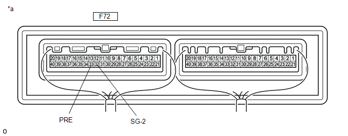
(e) Measure the voltage according to the value(s) in the table below.
|
*a |
Component with harness connected (Air Conditioning Amplifier Assembly) |
- |
- |
Standard Voltage:
|
Tester Connection |
Condition |
Specified Condition |
|---|---|---|
|
F72-33 (PRE) - F72-32 (SG-2) |
Refrigerant pressure: Normal pressure (less than 3025 kPa (30.8 kgf/cm2, 439 psi) and more than 176 kPa (1.8 kgf/cm2, 26 psi)) |
0.74 to 4.61 V |
| OK | |
REPLACE AIR CONDITIONING AMPLIFIER ASSEMBLY |
| NG | |
REPLACE AIR CONDITIONER PRESSURE SENSOR |
|
15. |
REPAIR AIR CONDITIONING SYSTEM LEAK |
(a) Identify the area where refrigerant leaks from.
- for HFC-134a (R134a): Click here
- for HFO-1234yf (R1234yf): Click here
(b) Repair the identified area of the air conditioning system.
(c) Evacuate the air conditioning system.
|
Result |
Proceed to |
|---|---|
|
for HFC-134a (R134a) |
A |
|
for HFO-1234yf (R1234yf) |
B |
| A | |
CHARGE SYSTEM WITH REFRIGERANT |
| B | |
CHARGE SYSTEM WITH REFRIGERANT |
|
16. |
CHECK HARNESS AND CONNECTOR (AIR CONDITIONING AMPLIFIER ASSEMBLY - AIR CONDITIONER PRESSURE SENSOR) |
(a) Disconnect the F72 air conditioning amplifier assembly connector.
(b) Disconnect the A52 air conditioner pressure sensor connector.
(c) Measure the resistance according to the value(s) in the table below.
Standard Resistance:
|
Tester Connection |
Condition |
Specified Condition |
|---|---|---|
|
A52-1 (+) - F72-34 (S5-3) |
Always |
Below 1 Ω |
|
A52-3 (-) - F72-32 (SG-2) |
Always |
Below 1 Ω |
|
A52-1 (+) or F72-34 (S5-3) - Body ground |
Always |
10 kΩ or higher |
|
A52-3 (-) or F72-32 (SG-2) - Body ground |
Always |
10 kΩ or higher |
| OK | |
REPLACE AIR CONDITIONING AMPLIFIER ASSEMBLY |
| NG | |
REPAIR OR REPLACE HARNESS OR CONNECTOR |
 Compressor Solenoid Circuit (B1451)
DESCRIPTION
In this circuit, the compressor with pulley assembly (compressor solenoid) receives
a refrigerant compression demand signal from the air conditioning amplifier assembly.
Based on this ...
 Room Temperature Sensor Circuit (B1411)
DESCRIPTION
The cooler thermistor (room temperature sensor) is installed in the instrument
panel to detect the cabin temperature, which is used to control the air conditioning
system. The resista ...
Other materials:
Toyota CH-R Service Manual > Lighting (ext): Headlight Leveling Switch
Components
COMPONENTS
ILLUSTRATION
*1
HEADLIGHT LEVELING SWITCH
*2
INSTRUMENT CLUSTER FINISH PANEL SUB-ASSEMBLY
Removal
REMOVAL
PROCEDURE
1. REMOVE INSTRUMENT CLUSTER FINISH PANEL SUB-ASSEMBLY
Click here
2. REMOVE HEADLIGHT LE ...
Toyota CH-R Service Manual > Steering Lock System: System Diagram
SYSTEM DIAGRAM
Circuit Description
Component
Outline
Steering Lock ECU (Steering Lock Actuator or Upper Bracket Assembly)
The steering is locked and unlocked by communicating with the
certification ECU (smart key ECU assembly) and ...
Toyota C-HR (AX20) 2023-2026 Owner's Manual
Toyota CH-R Owners Manual
- For safety and security
- Instrument cluster
- Operation of each component
- Driving
- Interior features
- Maintenance and care
- When trouble arises
- Vehicle specifications
- For owners
Toyota CH-R Service Manual
- Introduction
- Maintenance
- Audio / Video
- Cellular Communication
- Navigation / Multi Info Display
- Park Assist / Monitoring
- Brake (front)
- Brake (rear)
- Brake Control / Dynamic Control Systems
- Brake System (other)
- Parking Brake
- Axle And Differential
- Drive Shaft / Propeller Shaft
- K114 Cvt
- 3zr-fae Battery / Charging
- Networking
- Power Distribution
- Power Assist Systems
- Steering Column
- Steering Gear / Linkage
- Alignment / Handling Diagnosis
- Front Suspension
- Rear Suspension
- Tire / Wheel
- Tire Pressure Monitoring
- Door / Hatch
- Exterior Panels / Trim
- Horn
- Lighting (ext)
- Mirror (ext)
- Window / Glass
- Wiper / Washer
- Door Lock
- Heating / Air Conditioning
- Interior Panels / Trim
- Lighting (int)
- Meter / Gauge / Display
- Mirror (int)
- Power Outlets (int)
- Pre-collision
- Seat
- Seat Belt
- Supplemental Restraint Systems
- Theft Deterrent / Keyless Entry

0.0116