Toyota CH-R Service Manual: Removal
REMOVAL
CAUTION / NOTICE / HINT
The necessary procedures (adjustment, calibration, initialization, or registration) that must be performed after parts are removed, installed, or replaced during the airbag sensor assembly removal/installation are shown below.
Necessary Procedure After Parts Removed/Installed/Replaced|
Replacement Part or Procedure |
Necessary Procedures |
Effects / Inoperative when not performed |
Link |
|---|---|---|---|
|
Disconnect cable from negative battery terminal |
Initialize back door lock |
Power door lock control system |
|
|
Memorize steering angle neutral point |
Lane departure alert system (w/ Steering Control) |
|
|
|
Pre-collision system |
|||
|
Replacement of the airbag sensor assembly |
|
|
|
|
Deterioration of fuel efficiency |
|
PROCEDURE
1. PRECAUTION
CAUTION:
Be sure to read Precaution thoroughly before servicing.
Click here .gif)
.png)
NOTICE:
After turning the ignition switch off, waiting time may be required before disconnecting the cable from the negative (-) battery terminal. Therefore, make sure to read the disconnecting the cable from the negative (-) battery terminal notices before proceeding with work.
Click here
2. DISCONNECT CABLE FROM NEGATIVE BATTERY TERMINAL
Click here
.png)
- Wait at least 90 seconds after disconnecting the cable from the negative (-) battery terminal to disable the SRS system.
- If an SRS part is accidentally deployed, it may cause a serious injury.
NOTICE:
When disconnecting the cable, some systems need to be initialized after the cable is reconnected.
Click here
3. REMOVE REAR CONSOLE BOX ASSEMBLY
Click here
4. REMOVE REAR NO. 2 AIR DUCT (w/ Rear Air Duct)
(a) Disengage the claws to remove the rear No. 2 air duct as shown in the illustration.
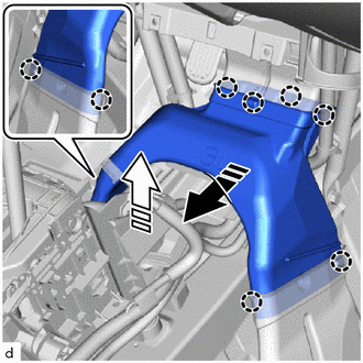
.png) |
Remove in this direction (1) |
.png) |
Remove in this direction (2) |
5. REMOVE AIRBAG SENSOR ASSEMBLY
(a) Check that the ignition switch off.
(b) Check that the cable is disconnected from the negative (-) battery terminal.
CAUTION:
Wait at least 90 seconds after disconnecting the cable from the negative (-) battery terminal to disable the SRS system.
|
(c) Remove the clip and turn back the front floor carpet assembly as shown in the illustration (for LH side). |
|
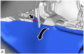
|
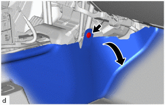
(d) Remove the clip and turn back the front floor carpet assembly as shown in the illustration (for RH side). |
|
(e) Disconnect the connectors from the airbag sensor assembly as shown in the illustration.
NOTICE:
When disconnecting any airbag connector, take care not to damage the airbag wire harness.
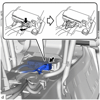
|
|
Release in this direction |
|
(f) Remove the 3 bolts and airbag sensor assembly. |
|
.png)
 Installation
INSTALLATION
PROCEDURE
1. INSTALL AIRBAG SENSOR ASSEMBLY
(a) Check that the ignition switch off.
(b) Check that the cable is disconnected from the negative (-) battery terminal.
CAUTION:
Wait at ...

Other materials:
Toyota CH-R Service Manual > Smart Key System(for Entry Function): Front Passenger Side Door Entry Lock Function does not Operate
DESCRIPTION
If the entry lock function does not operate for the front passenger door only,
but the entry unlock function operates, the request code is being transmitted properly
from the for passenger door. In this case, there may be a problem related to the
lock sensor (connection between th ...
Toyota CH-R Service Manual > Vehicle Stability Control System: Fail-safe Chart
FAIL-SAFE CHART
FAIL-SAFE OPERATION
If there is a problem with sensor signals or actuator systems, the skid
control ECU prohibits power supply to the brake actuator assembly and informs
the ECM of a VSC system malfunction.
The brake actuator assembly turns off the solenoids and t ...
Toyota C-HR (AX20) 2023-2026 Owner's Manual
Toyota CH-R Owners Manual
- For safety and security
- Instrument cluster
- Operation of each component
- Driving
- Interior features
- Maintenance and care
- When trouble arises
- Vehicle specifications
- For owners
Toyota CH-R Service Manual
- Introduction
- Maintenance
- Audio / Video
- Cellular Communication
- Navigation / Multi Info Display
- Park Assist / Monitoring
- Brake (front)
- Brake (rear)
- Brake Control / Dynamic Control Systems
- Brake System (other)
- Parking Brake
- Axle And Differential
- Drive Shaft / Propeller Shaft
- K114 Cvt
- 3zr-fae Battery / Charging
- Networking
- Power Distribution
- Power Assist Systems
- Steering Column
- Steering Gear / Linkage
- Alignment / Handling Diagnosis
- Front Suspension
- Rear Suspension
- Tire / Wheel
- Tire Pressure Monitoring
- Door / Hatch
- Exterior Panels / Trim
- Horn
- Lighting (ext)
- Mirror (ext)
- Window / Glass
- Wiper / Washer
- Door Lock
- Heating / Air Conditioning
- Interior Panels / Trim
- Lighting (int)
- Meter / Gauge / Display
- Mirror (int)
- Power Outlets (int)
- Pre-collision
- Seat
- Seat Belt
- Supplemental Restraint Systems
- Theft Deterrent / Keyless Entry

0.0075