Toyota CH-R Service Manual: Installation
INSTALLATION
PROCEDURE
1. INSTALL AIRBAG SENSOR ASSEMBLY
(a) Check that the ignition switch off.
(b) Check that the cable is disconnected from the negative (-) battery terminal.
CAUTION:
Wait at least 90 seconds after disconnecting the cable from the negative (-) battery terminal to disable the SRS system.
.png)
|
(c) Install the airbag sensor assembly with the 3 bolts. Torque: 17.5 N·m {178 kgf·cm, 13 ft·lbf} NOTICE:
|
|
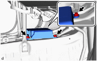
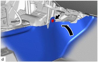
(d) Connect the connectors to the airbag sensor assembly as shown in the illustration.
.png) |
Install in this direction |
NOTICE:
When connecting any airbag connector, take care not to damage the airbag wire harness.
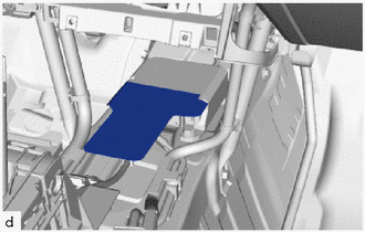
(e) w/o Rear Air Duct:
|
(1) Check that the waterproof sheet is properly set. |
|
(f) Check that there is no looseness in the installed parts of the airbag sensor assembly.
|
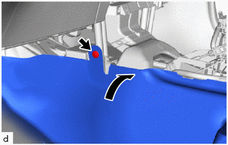
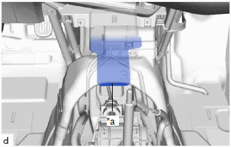
(g) Return the front floor carpet assembly and install the clip as shown in the illustration (for LH side). |
|
|
(h) Return the front floor carpet assembly and install the clip as shown in the illustration (for RH side). |
|
2. INSTALL REAR NO. 2 AIR DUCT (w/ Rear Air Duct)
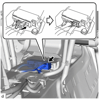
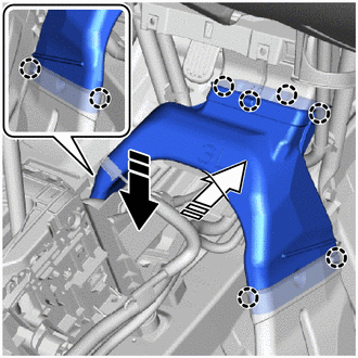
(a) Engage the claws to install the rear No. 2 air duct as shown in the illustration.
|
|
Install in this direction (1) |
.png) |
Install in this direction (2) |
|
(b) Check that the waterproof sheet is properly set as shown in the illustration. |
|
3. INSTALL REAR CONSOLE BOX ASSEMBLY
Click here .gif)
4. CONNECT CABLE TO NEGATIVE BATTERY TERMINAL
Click here
NOTICE:
When disconnecting the cable, some systems need to be initialized after the cable is reconnected.
Click here
5. PERFORM DIAGNOSTIC SYSTEM CHECK
Click here
6. INSPECT SRS WARNING LIGHT
Click here
7. PERFORM YAW RATE AND ACCELERATION SENSOR ZERO POINT CALIBRATION
(a) When the airbag sensor assembly is replaced, perform zero point calibration.
Click here
HINT:
The yaw rate and acceleration sensor is built into the airbag sensor assembly.
 On-vehicle Inspection
ON-VEHICLE INSPECTION
CAUTION / NOTICE / HINT
CAUTION:
Be sure to correctly follow the removal and installation procedures for the airbag
sensor assembly.
PROCEDURE
1. INSPECT AIRBAG SENSOR ASS ...
 Removal
REMOVAL
CAUTION / NOTICE / HINT
The necessary procedures (adjustment, calibration, initialization, or registration)
that must be performed after parts are removed, installed, or replaced during th ...
Other materials:
Toyota CH-R Service Manual > Front Door Outside Moulding: Disassembly
DISASSEMBLY
CAUTION / NOTICE / HINT
HINT:
Use the same procedure for the RH and LH sides.
The procedure listed below is for the LH side.
PROCEDURE
1. REMOVE FRONT DOOR UPPER OUTSIDE MOULDING PAD
(a) Remove the front door upper outside moulding pad.
...
Toyota CH-R Service Manual > Lighting (ext): Headlight Leveling Switch
Components
COMPONENTS
ILLUSTRATION
*1
HEADLIGHT LEVELING SWITCH
*2
INSTRUMENT CLUSTER FINISH PANEL SUB-ASSEMBLY
Removal
REMOVAL
PROCEDURE
1. REMOVE INSTRUMENT CLUSTER FINISH PANEL SUB-ASSEMBLY
Click here
2. REMOVE HEADLIGHT LE ...
Toyota C-HR (AX20) 2023-2026 Owner's Manual
Toyota CH-R Owners Manual
- For safety and security
- Instrument cluster
- Operation of each component
- Driving
- Interior features
- Maintenance and care
- When trouble arises
- Vehicle specifications
- For owners
Toyota CH-R Service Manual
- Introduction
- Maintenance
- Audio / Video
- Cellular Communication
- Navigation / Multi Info Display
- Park Assist / Monitoring
- Brake (front)
- Brake (rear)
- Brake Control / Dynamic Control Systems
- Brake System (other)
- Parking Brake
- Axle And Differential
- Drive Shaft / Propeller Shaft
- K114 Cvt
- 3zr-fae Battery / Charging
- Networking
- Power Distribution
- Power Assist Systems
- Steering Column
- Steering Gear / Linkage
- Alignment / Handling Diagnosis
- Front Suspension
- Rear Suspension
- Tire / Wheel
- Tire Pressure Monitoring
- Door / Hatch
- Exterior Panels / Trim
- Horn
- Lighting (ext)
- Mirror (ext)
- Window / Glass
- Wiper / Washer
- Door Lock
- Heating / Air Conditioning
- Interior Panels / Trim
- Lighting (int)
- Meter / Gauge / Display
- Mirror (int)
- Power Outlets (int)
- Pre-collision
- Seat
- Seat Belt
- Supplemental Restraint Systems
- Theft Deterrent / Keyless Entry

0.0067