Toyota CH-R Service Manual: Inspection
INSPECTION
PROCEDURE
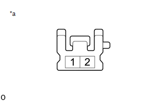
1. INSPECT FRONT SEATBACK HEATER ASSEMBLY LH
|
(a) for TMC Made: (1) Check the resistance.
|
|
|
(b) for TMMT Made: (1) Check the resistance.
|
|
2. INSPECT FRONT SEATBACK HEATER ASSEMBLY RH
|
(a) for TMC Made: (1) Check the resistance.
|
|
|
(b) for TMMT Made: (1) Check the resistance.
|
|
 Removal
REMOVAL
CAUTION / NOTICE / HINT
The necessary procedures (adjustment, calibration, initialization, or registration)
that must be performed after parts are removed, installed, or replaced during th ...
 Installation
INSTALLATION
CAUTION / NOTICE / HINT
CAUTION:
Be sure to read Precaution thoroughly before servicing.
Click here
Wear protective gloves. Sharp areas on the parts may inj ...
Other materials:
Toyota CH-R Service Manual > Theft Deterrent / Keyless Entry: Electrical Key Oscillator(for Outside Luggage Compartment)
Components
COMPONENTS
ILLUSTRATION
*1
ELECTRICAL KEY ANTENNA
-
-
N*m (kgf*cm, ft.*lbf): Specified torque
-
-
Installation
INSTALLATION
PROCEDURE
1. INSTALL ELECTRICAL KEY ANTENNA
(a) En ...
Toyota CH-R Service Manual > Glove Box Light: Inspection
INSPECTION
PROCEDURE
1. INSPECT GLOVE BOX LIGHT ASSEMBLY
(a) Check that the LED illuminates.
(1) Apply battery voltage to the glove box light assembly and check that
the LED illuminates.
OK:
Measurement Condition
Specified Condition
...
Toyota C-HR (AX20) 2023-2026 Owner's Manual
Toyota CH-R Owners Manual
- For safety and security
- Instrument cluster
- Operation of each component
- Driving
- Interior features
- Maintenance and care
- When trouble arises
- Vehicle specifications
- For owners
Toyota CH-R Service Manual
- Introduction
- Maintenance
- Audio / Video
- Cellular Communication
- Navigation / Multi Info Display
- Park Assist / Monitoring
- Brake (front)
- Brake (rear)
- Brake Control / Dynamic Control Systems
- Brake System (other)
- Parking Brake
- Axle And Differential
- Drive Shaft / Propeller Shaft
- K114 Cvt
- 3zr-fae Battery / Charging
- Networking
- Power Distribution
- Power Assist Systems
- Steering Column
- Steering Gear / Linkage
- Alignment / Handling Diagnosis
- Front Suspension
- Rear Suspension
- Tire / Wheel
- Tire Pressure Monitoring
- Door / Hatch
- Exterior Panels / Trim
- Horn
- Lighting (ext)
- Mirror (ext)
- Window / Glass
- Wiper / Washer
- Door Lock
- Heating / Air Conditioning
- Interior Panels / Trim
- Lighting (int)
- Meter / Gauge / Display
- Mirror (int)
- Power Outlets (int)
- Pre-collision
- Seat
- Seat Belt
- Supplemental Restraint Systems
- Theft Deterrent / Keyless Entry

0.0098