Toyota CH-R Service Manual: Parking Brake Switch Circuit
DESCRIPTION
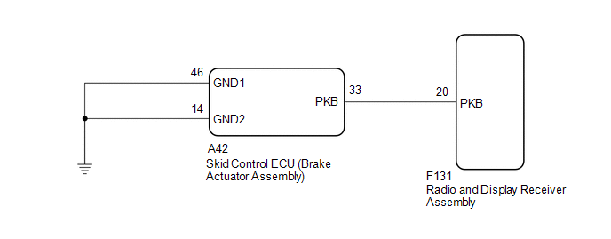
This circuit is from the skid control ECU (brake actuator assembly) to the radio and display receiver assembly.
WIRING DIAGRAM
PROCEDURE
|
1. |
CHECK ELECTRIC PARKING BRAKE SYSTEM |
(a) Check the operation of the electric parking brake.
| NG | .gif) |
GO TO ELECTRIC PARKING BRAKE SYSTEM |
|
.gif)
|
2. |
CHECK HARNESS AND CONNECTOR (SKID CONTROL ECU (BRAKE ACTUATOR ASSEMBLY) - RADIO AND DISPLAY RECEIVER ASSEMBLY) |
(a) Disconnect the F131 radio and display receiver assembly connector.
(b) Disconnect the A42 skid control ECU (brake actuator assembly) connector.
(c) Measure the resistance according to the value(s) in the table below.
Standard Resistance:
|
Tester Connection |
Condition |
Specified Condition |
|---|---|---|
|
F131-20 (PKB) - A42-33 (PKB) |
Always |
Below 1 Ω |
|
F131-20 (PKB) or A42-33 (PKB) - Body ground |
Always |
10 kΩ or higher |
| OK | |
PROCEED TO NEXT SUSPECTED AREA SHOWN IN PROBLEM SYMPTOMS TABLE |
| NG | |
REPAIR OR REPLACE HARNESS OR CONNECTOR |
 Illumination Circuit
DESCRIPTION
Power is supplied to the radio and display receiver assembly and steering pad
switch assembly illumination when the light control switch is in the tail or head
position.
WIRING DIAGR ...
 Speaker Circuit
DESCRIPTION
Thus sound cannot be heard from the speakers even if there is no malfunction
in the DCM (telematics transceiver) or speakers.
WIRING DIAGRAM
CAUTION / NOTICE / HINT
NOTICE:
...
Other materials:
Toyota CH-R Service Manual > Personal Light: Inspection
INSPECTION
PROCEDURE
1. INSPECT MAP LIGHT ASSEMBLY
(a) Check the map light.
(1) Apply battery voltage to the map light assembly and check that the
map light comes on.
OK:
Battery Connection
Switch Condition
Specified Cond ...
Toyota CH-R Service Manual > Smart Key System(for Entry Function): Front Passenger Side Door Entry Unlock Function does not Operate
DESCRIPTION
If the entry unlock function does not operate for the front passenger door only,
but the entry lock function operates, the request code is being transmitted properly
from the front passenger door. In this case, there may be a problem related to the
unlock sensor (connection betwee ...
Toyota C-HR (AX20) 2023-2026 Owner's Manual
Toyota CH-R Owners Manual
- For safety and security
- Instrument cluster
- Operation of each component
- Driving
- Interior features
- Maintenance and care
- When trouble arises
- Vehicle specifications
- For owners
Toyota CH-R Service Manual
- Introduction
- Maintenance
- Audio / Video
- Cellular Communication
- Navigation / Multi Info Display
- Park Assist / Monitoring
- Brake (front)
- Brake (rear)
- Brake Control / Dynamic Control Systems
- Brake System (other)
- Parking Brake
- Axle And Differential
- Drive Shaft / Propeller Shaft
- K114 Cvt
- 3zr-fae Battery / Charging
- Networking
- Power Distribution
- Power Assist Systems
- Steering Column
- Steering Gear / Linkage
- Alignment / Handling Diagnosis
- Front Suspension
- Rear Suspension
- Tire / Wheel
- Tire Pressure Monitoring
- Door / Hatch
- Exterior Panels / Trim
- Horn
- Lighting (ext)
- Mirror (ext)
- Window / Glass
- Wiper / Washer
- Door Lock
- Heating / Air Conditioning
- Interior Panels / Trim
- Lighting (int)
- Meter / Gauge / Display
- Mirror (int)
- Power Outlets (int)
- Pre-collision
- Seat
- Seat Belt
- Supplemental Restraint Systems
- Theft Deterrent / Keyless Entry

0.0082