Toyota CH-R Service Manual: Removal
REMOVAL
CAUTION / NOTICE / HINT
The necessary procedures (adjustment, calibration, initialization, or registration) that must be performed after parts are removed, installed, or replaced during the front seatback heater assembly removal/installation are shown below.
Necessary Procedure After Parts Removed/Installed/Replaced|
Replacement Part or Procedure |
Necessary Procedures |
Effects / Inoperative when not performed |
Link |
|---|---|---|---|
|
Disconnect cable from negative battery terminal |
Initialize back door lock |
Power door lock control system |
|
|
Memorize steering angle neutral point |
Lane departure alert system (w/ Steering Control) |
|
|
|
Pre-collision system |
CAUTION:
- Be sure to read Precaution thoroughly before servicing.
.png)
Click here
.gif)
- Wear protective gloves. Sharp areas on the parts may injure your hands.
HINT:
- Use the same procedure for the driver side and front passenger side.
- The procedure listed below is for the driver side.
PROCEDURE
1. REMOVE FRONT SEAT ASSEMBLY
Click here
2. DISCONNECT SEPARATE TYPE FRONT SEATBACK COVER
Click here
3. REMOVE VERTICAL ADJUSTING HANDLE (w/ Vertical Adjuster)
Click here
4. REMOVE RECLINING HINGE OUTER COVER
Click here
5. REMOVE RECLINING ADJUSTER RELEASE HANDLE
Click here
6. REMOVE SEAT ADJUSTER COVER CAP (w/ Vertical Adjuster)
Click here
7. REMOVE FRONT SEAT CUSHION SHIELD (for Driver Side)
Click here
8. REMOVE FRONT SEAT INNER CUSHION SHIELD (for Driver Side)
Click here
9. REMOVE FRONT SEAT CUSHION SHIELD (for Front Passenger Side)
Click here
10. REMOVE FRONT SEAT INNER CUSHION SHIELD (for Front Passenger Side)
Click here
11. REMOVE SEPARATE TYPE FRONT SEATBACK ASSEMBLY
Click here
12. REMOVE FRONT SEAT HEADREST SUPPORT
Click here
13. REMOVE SEPARATE TYPE FRONT SEATBACK COVER WITH PAD
Click here
14. REMOVE SEPARATE TYPE FRONT SEATBACK COVER
Click here
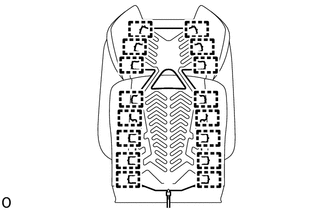
15. REMOVE FRONT SEATBACK HEATER ASSEMBLY
|
(a) Remove the 16 tag pins and front seatback heater assembly from the separate type front seatback cover. |
|
 Components
COMPONENTS
ILLUSTRATION
*A
for Driver Side
*B
for Front Passenger Side
*C
w/ Vertical Adjuster
-
-
...
 Inspection
INSPECTION
PROCEDURE
1. INSPECT FRONT SEATBACK HEATER ASSEMBLY LH
(a) for TMC Made:
(1) Check the resistance.
Measure the resistance according to the value(s) in the tab ...
Other materials:
Toyota CH-R Service Manual > Main Body Ecu: Installation
INSTALLATION
PROCEDURE
1. INSTALL MAIN BODY ECU (MULTIPLEX NETWORK BODY ECU)
NOTICE:
Make sure that the connecting surfaces are free of foreign matter.
Do not touch the main body ECU (multiplex network body ECU) connector.
(a) Set the main body ECU (multiplex network bod ...
Toyota CH-R Service Manual > Rocker Panel Moulding: Reassembly
REASSEMBLY
PROCEDURE
1. INSTALL ROCKER PANEL MOULDING PAD
HINT:
Using the same procedure, remove every rocker panel moulding pad.
When installing the rocker panel moulding pad, heat the rocker panel
moulding using a heat light.
Heating Temperature:
Item
...
Toyota C-HR (AX20) 2023-2026 Owner's Manual
Toyota CH-R Owners Manual
- For safety and security
- Instrument cluster
- Operation of each component
- Driving
- Interior features
- Maintenance and care
- When trouble arises
- Vehicle specifications
- For owners
Toyota CH-R Service Manual
- Introduction
- Maintenance
- Audio / Video
- Cellular Communication
- Navigation / Multi Info Display
- Park Assist / Monitoring
- Brake (front)
- Brake (rear)
- Brake Control / Dynamic Control Systems
- Brake System (other)
- Parking Brake
- Axle And Differential
- Drive Shaft / Propeller Shaft
- K114 Cvt
- 3zr-fae Battery / Charging
- Networking
- Power Distribution
- Power Assist Systems
- Steering Column
- Steering Gear / Linkage
- Alignment / Handling Diagnosis
- Front Suspension
- Rear Suspension
- Tire / Wheel
- Tire Pressure Monitoring
- Door / Hatch
- Exterior Panels / Trim
- Horn
- Lighting (ext)
- Mirror (ext)
- Window / Glass
- Wiper / Washer
- Door Lock
- Heating / Air Conditioning
- Interior Panels / Trim
- Lighting (int)
- Meter / Gauge / Display
- Mirror (int)
- Power Outlets (int)
- Pre-collision
- Seat
- Seat Belt
- Supplemental Restraint Systems
- Theft Deterrent / Keyless Entry

0.0098