Toyota CH-R Service Manual: Installation
INSTALLATION
CAUTION / NOTICE / HINT
HINT:
- Use the same procedure for the RH side and LH side.
- The following procedure is for the LH side.
PROCEDURE
1. INSTALL REAR SUSPENSION SUPPORT ASSEMBLY
(a) Secure the rear suspension support assembly in a vise using aluminum plates.
NOTICE:
Do not overtighten the vise.
(b) Install the rear suspension support assembly to the rear shock absorber assembly.
(c) Apply a few drops of adhesive to the threads of a new rear support to rear shock absorber nut.
Adhesive:
Toyota Genuine Adhesive 1324, Three Bond 1324 or equivalent
|
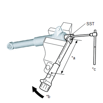
(d) Using SST and a 6 mm hexagon socket wrench, hold the rear shock absorber rod and tighten a new rear support to rear shock absorber nut. SST: 09729-97202 Torque: Specified tightening torque : 25 N·m {255 kgf·cm, 18 ft·lbf} NOTICE: Securely insert the 6 mm hexagon socket wrench into the rear shock absorber rod to prevent damage to the rear shock absorber assembly when tightening the rear support to rear shock absorber nut. HINT:
|
|
2. INSTALL REAR SHOCK ABSORBER CAP
(a) Install the rear shock absorber cap to the rear shock absorber assembly.
3. TEMPORARILY INSTALL REAR SHOCK ABSORBER ASSEMBLY
(a) Temporarily install the rear shock absorber assembly to the rear axle carrier sub-assembly with the nut.
NOTICE:
Hold the rear axle carrier pin while rotating the nut.
4. STABILIZE SUSPENSION
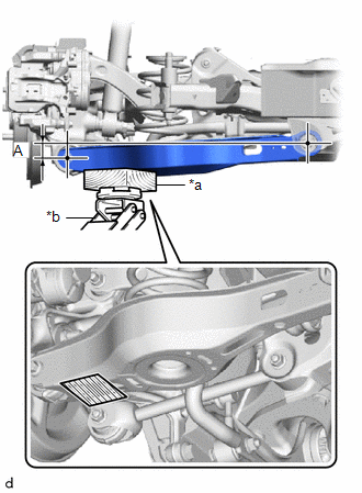
(a) Using a jack and a wooden block, apply load to the suspension so that the rear No. 2 suspension arm assembly is positioned as shown in the illustration.
Standard Length A:
34.5 mm (1.36 in.)
.png)
- Do not raise the jack up too high.
- The vehicle could fall, resulting in a serious accident.
|
*a |
Wooden Block |
|
*b |
Jack |
.png) |
Wooden Block Placement Location |
NOTICE:
- When jacking up the rear No. 2 suspension arm assembly, be sure to jack it up slowly.
- Make sure to perform this operation with the vehicle kept as low as possible.
5. TEMPORARILY INSTALL REAR UPPER CONTROL ARM ASSEMBLY
(a) Temporarily install the rear upper control arm assembly to the rear axle carrier sub-assembly with the bolt and nut.
NOTICE:
- Insert the bolt with the threaded end facing the rear of the vehicle.
- Because the nut has its own stopper, do not turn the nut. Tighten the bolt with the nut secured.
6. CONNECT REAR SHOCK ABSORBER ASSEMBLY
|
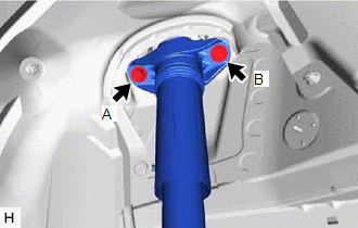
(a) Connect the rear shock absorber assembly to the vehicle with the 2 bolts. Torque: 55 N·m {561 kgf·cm, 41 ft·lbf} NOTICE: Temporarily tighten bolt A and then fully tighten the 2 bolts in the order of B and A. |
|
7. INSTALL REAR SHOCK ABSORBER ASSEMBLY
|
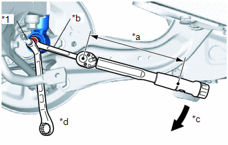
(a) Using a ball joint lock nut wrench fully tighten the rear shock absorber assembly with the nut. Torque: Specified tightening torque : 125 N·m {1275 kgf·cm, 92 ft·lbf} NOTICE: Hold the rear axle carrier pin while rotating the nut. HINT:
|
|
8. INSTALL REAR UPPER CONTROL ARM ASSEMBLY
(a) Install the rear upper control arm assembly to the rear axle carrier sub-assembly with the bolt.
Torque:
73 N·m {744 kgf·cm, 54 ft·lbf}
NOTICE:
Because the nut has its own stopper, do not turn the nut. Tighten the bolt with the nut secured.
9. INSTALL REAR STABILIZER LINK ASSEMBLY
Click here
.gif)
10. INSTALL REAR HEIGHT CONTROL SENSOR SUB-ASSEMBLY LH (w/ Height Control Sensor)
Click here
11. INSTALL REAR WHEEL
Click here
12. INSPECT AND ADJUST REAR WHEEL ALIGNMENT
Click here
13. PERFORM INITIALIZATION (w/ Height Control Sensor)
Click here
 Disposal
DISPOSAL
PROCEDURE
1. DISPOSE OF REAR SHOCK ABSORBER ASSEMBLY
(a) Extend the piston rod and secure the rear shock absorber assembly
at an angle in a vise.
...

Other materials:
Toyota CH-R Service Manual > Airbag System: Dtc Check / Clear
DTC CHECK / CLEAR
DTC CHECK (USING SST CHECK WIRE)
(a) Check for DTCs (Current DTCs).
(1) Turn the ignition switch ON, and wait for at least 60 seconds.
(2) Using SST, connect terminals TC and CG of the DLC3.
SST: 09843-18040
NOTICE:
Connect the correct terminals to avoid a malfunction.
(b ...
Toyota CH-R Owners Manual > Do-it-yourself maintenance: Tires
Replace or rotate tires in accordance with maintenance schedules
and treadwear.
Checking tires
Check if the treadwear indicators are showing on the tires. Also check the tires
for uneven wear, such as excessive wear on one side of the tread.
Check the spare tire condition and pressure if not ...
Toyota C-HR (AX20) 2023-2026 Owner's Manual
Toyota CH-R Owners Manual
- For safety and security
- Instrument cluster
- Operation of each component
- Driving
- Interior features
- Maintenance and care
- When trouble arises
- Vehicle specifications
- For owners
Toyota CH-R Service Manual
- Introduction
- Maintenance
- Audio / Video
- Cellular Communication
- Navigation / Multi Info Display
- Park Assist / Monitoring
- Brake (front)
- Brake (rear)
- Brake Control / Dynamic Control Systems
- Brake System (other)
- Parking Brake
- Axle And Differential
- Drive Shaft / Propeller Shaft
- K114 Cvt
- 3zr-fae Battery / Charging
- Networking
- Power Distribution
- Power Assist Systems
- Steering Column
- Steering Gear / Linkage
- Alignment / Handling Diagnosis
- Front Suspension
- Rear Suspension
- Tire / Wheel
- Tire Pressure Monitoring
- Door / Hatch
- Exterior Panels / Trim
- Horn
- Lighting (ext)
- Mirror (ext)
- Window / Glass
- Wiper / Washer
- Door Lock
- Heating / Air Conditioning
- Interior Panels / Trim
- Lighting (int)
- Meter / Gauge / Display
- Mirror (int)
- Power Outlets (int)
- Pre-collision
- Seat
- Seat Belt
- Supplemental Restraint Systems
- Theft Deterrent / Keyless Entry

0.009