Toyota CH-R Service Manual: Installation
INSTALLATION
CAUTION / NOTICE / HINT
HINT:
- Use the same procedure for the RH side and LH side.
- The following procedure is for the LH side.
PROCEDURE
1. REPAIR INSTRUCTION
Click here
.gif)
2. INSTALL REAR DOOR OUTSIDE STRIPE
(a) Refer to the illustration to position a new rear door outside stripe.
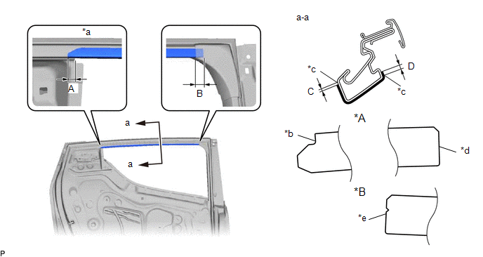
|
*A |
LH Side |
*B |
RH Side |
|
*a |
Point A |
*b |
Point B |
|
*c |
Edge of Curved Surface |
*d |
Straight |
|
*e |
Triangle |
- |
- |
Standard Measurement:
|
Area |
Measurement |
Area |
Measurement |
|---|---|---|---|
|
A |
1.0 mm (0.0394 in.) |
B |
10.0 mm (0.394 in.) |
|
C |
1.0 mm (0.0394 in.) |
D |
2.5 mm (0.0984 in.) |
(b) Remove the release paper and install the rear door outside stripe.
HINT:
Align the point (B) on the rear door outside stripe with the point (A) on the door frame and install the rear door outside stripe.
3. INSTALL REAR DOOR LOWER OUTSIDE STRIPE
(a) Refer to the illustration to position a new rear door lower outside stripe.
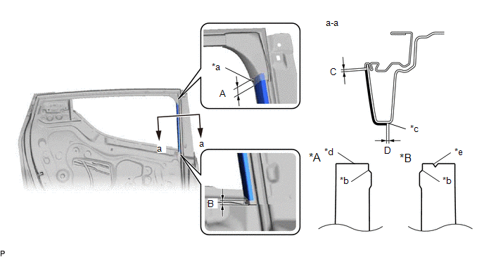
|
*A |
LH Side |
*B |
RH Side |
|
*a |
Point A |
*b |
Point B |
|
*c |
Edge of Curved Surface |
*d |
Straight |
|
*e |
Triangle |
- |
- |
Standard Measurement:
|
Area |
Measurement |
Area |
Measurement |
|---|---|---|---|
|
A |
10.0 mm (0.394 in.) |
B |
5.0 mm (0.197 in.) |
|
C |
-1.0 to 1.0 mm (-0.0394 to 0.0394 in.) |
D |
1.0 mm (0.0394 in.) |
(b) Remove the release paper and install the rear door lower outside stripe.
HINT:
Align the point (B) on the rear door lower outside stripe with the point (A) on the door frame and install the rear door lower outside stripe.
4. INSTALL REAR DOOR QUARTER WINDOW GLASS
Click here
5. INSTALL REAR DOOR GLASS RUN
Click here
6. INSTALL REAR DOOR FRAME GARNISH
Click here
7. INSTALL REAR DOOR GLASS SUB-ASSEMBLY
Click here
8. INSTALL REAR DOOR WINDOW REAR LOWER FRAME SUB-ASSEMBLY
Click here
9. INSTALL REAR DOOR WEATHERSTRIP
Click here
10. INSTALL REAR DOOR SERVICE HOLE COVER
Click here
11. INSTALL REAR DOOR BELT SEAL
Click here
12. INSTALL REAR DOOR GLASS INNER WEATHERSTRIP
Click here
13. INSTALL REAR DOOR BELT REAR SEAL
Click here
14. INSTALL REAR DOOR TRIM BOARD SUB-ASSEMBLY
Click here
15. INSTALL REAR DOOR REAR FRAME BRACKET
Click here
16. INSTALL REAR POWER WINDOW REGULATOR SWITCH ASSEMBLY WITH REAR DOOR ARMREST BASE UPPER PANEL
Click here
17. INSTALL REAR DOOR INSIDE HANDLE BEZEL PLUG
Click here
18. CONNECT CABLE TO NEGATIVE BATTERY TERMINAL
Click here
NOTICE:
When disconnecting the cable, some systems need to be initialized after the cable is reconnected.
Click here
19. INITIALIZE POWER WINDOW CONTROL SYSTEM
Click here
20. INSPECT POWER WINDOW OPERATION
Click here
 Removal
REMOVAL
CAUTION / NOTICE / HINT
The necessary procedures (adjustment, calibration, initialization, or registration)
that must be performed after parts are removed and installed, or replaced during ...
 Front Bumper
...
Other materials:
Toyota CH-R Service Manual > Lighting System: Precaution
PRECAUTION
IGNITION SWITCH EXPRESSIONS
(a) The type of ignition switch used on this model differs depending on the specifications
of the vehicle. The expressions listed in the table below are used in this section.
Expression
Ignition Switch (Position)
Engine Swi ...
Toyota CH-R Service Manual > Smart Key System(for Start Function): Data List / Active Test
DATA LIST / ACTIVE TEST
DATA LIST
HINT:
Using the Techstream to read the Data List allows the values or states of switches,
sensors, actuators and other items to be read without removing any parts. This non-intrusive
inspection can be very useful because intermittent conditions or signals may ...
Toyota C-HR (AX20) 2023-2026 Owner's Manual
Toyota CH-R Owners Manual
- For safety and security
- Instrument cluster
- Operation of each component
- Driving
- Interior features
- Maintenance and care
- When trouble arises
- Vehicle specifications
- For owners
Toyota CH-R Service Manual
- Introduction
- Maintenance
- Audio / Video
- Cellular Communication
- Navigation / Multi Info Display
- Park Assist / Monitoring
- Brake (front)
- Brake (rear)
- Brake Control / Dynamic Control Systems
- Brake System (other)
- Parking Brake
- Axle And Differential
- Drive Shaft / Propeller Shaft
- K114 Cvt
- 3zr-fae Battery / Charging
- Networking
- Power Distribution
- Power Assist Systems
- Steering Column
- Steering Gear / Linkage
- Alignment / Handling Diagnosis
- Front Suspension
- Rear Suspension
- Tire / Wheel
- Tire Pressure Monitoring
- Door / Hatch
- Exterior Panels / Trim
- Horn
- Lighting (ext)
- Mirror (ext)
- Window / Glass
- Wiper / Washer
- Door Lock
- Heating / Air Conditioning
- Interior Panels / Trim
- Lighting (int)
- Meter / Gauge / Display
- Mirror (int)
- Power Outlets (int)
- Pre-collision
- Seat
- Seat Belt
- Supplemental Restraint Systems
- Theft Deterrent / Keyless Entry

0.009