Toyota CH-R Service Manual: Removal
REMOVAL
CAUTION / NOTICE / HINT
The necessary procedures (adjustment, calibration, initialization, or registration) that must be performed after parts are removed, installed, or replaced during the front seat cushion heater assembly removal/installation are shown below.
Necessary Procedure After Parts Removed/Installed/Replaced|
Replacement Part or Procedure |
Necessary Procedures |
Effects/Inoperative when not performed |
Link |
|---|---|---|---|
|
Disconnect cable from negative battery terminal |
Initialize back door lock |
Power door lock control system |
|
|
Memorize steering angle neutral point |
Lane departure alert system (w/ Steering Control) |
|
|
|
Pre-collision system |
CAUTION:
- Be sure to read Precaution thoroughly before servicing.
Click here
.gif)
.png)
- Wear protective gloves. Sharp areas on the parts may injure your hands.
HINT:
- Use the same procedure for RHD and LHD vehicles.
- The procedure listed below is for LHD vehicles.
- Use the same procedure for the driver side and front passenger side.
- The procedure listed below is for the driver side.
PROCEDURE
1. REMOVE SEPARATE TYPE FRONT SEATBACK ASSEMBLY
Click here
2. REMOVE SEPARATE TYPE FRONT SEAT CUSHION COVER WITH PAD
Click here
3. REMOVE SEPARATE TYPE FRONT SEAT CUSHION COVER
Click here
4. REMOVE FRONT SEAT CUSHION HEATER ASSEMBLY
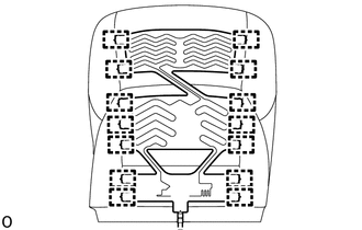
(a) Remove the 14 tag pins and front seat cushion heater assembly from the separate type front seat cushion cover.
 Inspection
INSPECTION
PROCEDURE
1. INSPECT FRONT SEAT CUSHION HEATER ASSEMBLY LH
(a) for TMC Made:
(1) Check the resistance.
Measure the resistance according to the value(s) in the ...
 Installation
INSTALLATION
CAUTION / NOTICE / HINT
CAUTION:
Be sure to read Precaution thoroughly before servicing.
Click here
Wear protective gloves. Sharp areas on the parts may inj ...
Other materials:
Toyota CH-R Service Manual > Pre-collision System: How To Proceed With Troubleshooting
CAUTION / NOTICE / HINT
HINT:
Use these procedures to troubleshoot the pre-collision system.
*: Use the Techstream.
PROCEDURE
1.
VEHICLE BROUGHT TO WORKSHOP
NEXT
2.
...
Toyota CH-R Service Manual > Immobiliser System(w/ Smart Key System): Engine Starter Communication Malfunction (B2779)
DESCRIPTION
If the remote engine start ECU does not respond to the certification ECU (smart
key ECU assembly) or the remote engine start ID is not registered, this DTC is stored.
HINT:
Registration status of the remote engine start ECU ID can be checked using the
"Wireless C Code" i ...
Toyota C-HR (AX20) 2023-2026 Owner's Manual
Toyota CH-R Owners Manual
- For safety and security
- Instrument cluster
- Operation of each component
- Driving
- Interior features
- Maintenance and care
- When trouble arises
- Vehicle specifications
- For owners
Toyota CH-R Service Manual
- Introduction
- Maintenance
- Audio / Video
- Cellular Communication
- Navigation / Multi Info Display
- Park Assist / Monitoring
- Brake (front)
- Brake (rear)
- Brake Control / Dynamic Control Systems
- Brake System (other)
- Parking Brake
- Axle And Differential
- Drive Shaft / Propeller Shaft
- K114 Cvt
- 3zr-fae Battery / Charging
- Networking
- Power Distribution
- Power Assist Systems
- Steering Column
- Steering Gear / Linkage
- Alignment / Handling Diagnosis
- Front Suspension
- Rear Suspension
- Tire / Wheel
- Tire Pressure Monitoring
- Door / Hatch
- Exterior Panels / Trim
- Horn
- Lighting (ext)
- Mirror (ext)
- Window / Glass
- Wiper / Washer
- Door Lock
- Heating / Air Conditioning
- Interior Panels / Trim
- Lighting (int)
- Meter / Gauge / Display
- Mirror (int)
- Power Outlets (int)
- Pre-collision
- Seat
- Seat Belt
- Supplemental Restraint Systems
- Theft Deterrent / Keyless Entry

0.0074