Toyota CH-R Service Manual: Vanity Light
Components
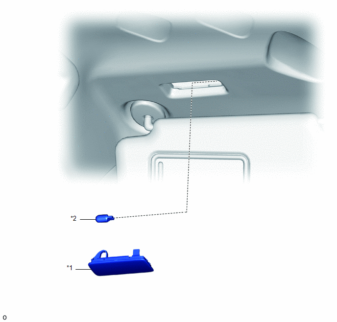
COMPONENTS
ILLUSTRATION
|
*1 |
VANITY LIGHT ASSEMBLY |
*2 |
VANITY LIGHT BULB |
Removal
REMOVAL
CAUTION / NOTICE / HINT
HINT:
- Use the same procedure for both the LH and RH sides.
- The procedure described below is for the LH side.
PROCEDURE
1. REMOVE VANITY LIGHT ASSEMBLY
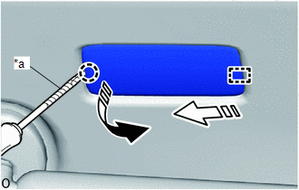
(a) Using a screwdriver with its tip wrapped in protective tape, disengage the claw and guide to remove the vanity light assembly from the roof headlining as shown in the illustration.
|
*a |
Protective Tape |
.png) |
Remove in this Direction (1) |
.png) |
Remove in this Direction (2) |
|
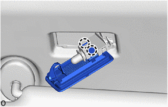
(b) Disengage the claws to remove the vanity light assembly from the bulb holder. |
|
2. REMOVE VANITY LIGHT BULB
Click here .gif)
Installation
INSTALLATION
CAUTION / NOTICE / HINT
HINT:
- Use the same procedure for both the LH and RH sides.
- The procedure described below is for the LH side.
PROCEDURE
1. INSTALL VANITY LIGHT BULB
Click here .gif)
2. INSTALL VANITY LIGHT ASSEMBLY
|
(a) Engage the claws to install the vanity light assembly to the bulb holder. |
|
.png)
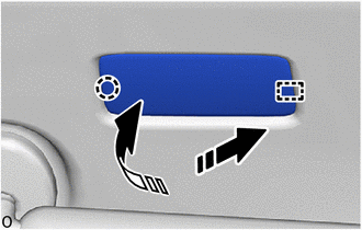
(b) Engage the guide and claw to install the vanity light assembly to the roof headlining as shown in the illustration.
.png) |
Install in this Direction (1) |
.png) |
Install in this Direction (2) |
 Room Light Bulb
Replacement
REPLACEMENT
PROCEDURE
1. REMOVE NO. 2 ROOM LIGHT BULB
(a) Using a screwdriver with its tip wrapped in protective tape, disengage the
claws to remove the room light lens as shown in ...
 Vanity Light Bulb
Replacement
REPLACEMENT
CAUTION / NOTICE / HINT
HINT:
Use the same procedure for both the LH and RH sides.
The procedure described below is for the LH side.
PROCEDURE
1. REMO ...
Other materials:
Toyota CH-R Service Manual > Meter / Gauge System: Lost Communication with ECM / PCM "A" (U0100,U0129,U0131,U0142,U0151,U0182,U0235,U023A)
DESCRIPTION
The combination meter assembly communicates with the ECM, brake actuator assembly
(skid control ECU), power steering ECU assembly, main body ECU (multiplex network
body ECU), airbag sensor assembly, headlight control ECU sub-assembly LH*1, front
camera module*2, millimeter wave ra ...
Toyota CH-R Service Manual > Brake Booster: Reassembly
REASSEMBLY
PROCEDURE
1. INSTALL VACUUM WARNING SWITCH ASSEMBLY
(a) Install a new check valve grommet to the brake booster assembly.
(b) Install the vacuum sensor assembly to the brake booster assembly
as shown in the illustration.
...
Toyota C-HR (AX20) 2023-2026 Owner's Manual
Toyota CH-R Owners Manual
- For safety and security
- Instrument cluster
- Operation of each component
- Driving
- Interior features
- Maintenance and care
- When trouble arises
- Vehicle specifications
- For owners
Toyota CH-R Service Manual
- Introduction
- Maintenance
- Audio / Video
- Cellular Communication
- Navigation / Multi Info Display
- Park Assist / Monitoring
- Brake (front)
- Brake (rear)
- Brake Control / Dynamic Control Systems
- Brake System (other)
- Parking Brake
- Axle And Differential
- Drive Shaft / Propeller Shaft
- K114 Cvt
- 3zr-fae Battery / Charging
- Networking
- Power Distribution
- Power Assist Systems
- Steering Column
- Steering Gear / Linkage
- Alignment / Handling Diagnosis
- Front Suspension
- Rear Suspension
- Tire / Wheel
- Tire Pressure Monitoring
- Door / Hatch
- Exterior Panels / Trim
- Horn
- Lighting (ext)
- Mirror (ext)
- Window / Glass
- Wiper / Washer
- Door Lock
- Heating / Air Conditioning
- Interior Panels / Trim
- Lighting (int)
- Meter / Gauge / Display
- Mirror (int)
- Power Outlets (int)
- Pre-collision
- Seat
- Seat Belt
- Supplemental Restraint Systems
- Theft Deterrent / Keyless Entry

0.0135