Toyota CH-R Service Manual: Room Light Bulb
Replacement
REPLACEMENT
PROCEDURE
1. REMOVE NO. 2 ROOM LIGHT BULB
(a) Using a screwdriver with its tip wrapped in protective tape, disengage the claws to remove the room light lens as shown in the illustration.
.png)
|
*a |
Protective Tape |
.png) |
Remove in this Direction |
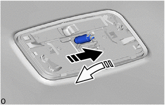
(b) Remove the No. 2 room light bulb as shown in the illustration.
|
|
Remove in this Direction (1) |
.png) |
Remove in this Direction (2) |
2. INSTALL NO. 2 ROOM LIGHT BULB
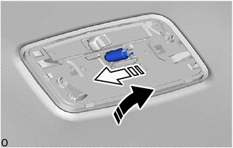
(a) Install the No. 2 room light bulb as shown in the illustration.
|
|
Install in this Direction (1) |
|
|
Install in this Direction (2) |
(b) Engage the claws to install the room light lens as shown in the illustration.
.png)
|
|
Install in this Direction |
 Room Light
Components
COMPONENTS
ILLUSTRATION
*1
NO. 1 ROOM LIGHT ASSEMBLY
*2
NO. 2 ROOM LIGHT BULB
*3
ROOM LIGHT LENS
*4 ...
 Vanity Light
Components
COMPONENTS
ILLUSTRATION
*1
VANITY LIGHT ASSEMBLY
*2
VANITY LIGHT BULB
Removal
REMOVAL
CAUTION / NOTICE / HINT
HINT:
...
Other materials:
Toyota CH-R Service Manual > Air Conditioning System(for Automatic Air Conditioning System With Top-mounted
Air Conditioner Pressure Sensor): Open in Ion Generator Circuit (B14B9)
DESCRIPTION
The ion generator sub-assembly operates when both the ion generator switch and
the blower switch are on. The air conditioning amplifier assembly sends a drive
signal to the ion generator sub-assembly. When the ion generator sub-assembly receives
the drive signal and starts to oper ...
Toyota CH-R Service Manual > Navigation System: Mute Signal Circuit between Radio Receiver and Telematics Transceiver
DESCRIPTION
The telematics transceiver sends a mute signal to the radio and display receiver
assembly.
The radio and display receiver assembly controls the volume according to the
mute signal from the telematics transceiver.
WIRING DIAGRAM
CAUTION / NOTICE / HINT
NOTICE:
Depending on the ...
Toyota C-HR (AX20) 2023-2026 Owner's Manual
Toyota CH-R Owners Manual
- For safety and security
- Instrument cluster
- Operation of each component
- Driving
- Interior features
- Maintenance and care
- When trouble arises
- Vehicle specifications
- For owners
Toyota CH-R Service Manual
- Introduction
- Maintenance
- Audio / Video
- Cellular Communication
- Navigation / Multi Info Display
- Park Assist / Monitoring
- Brake (front)
- Brake (rear)
- Brake Control / Dynamic Control Systems
- Brake System (other)
- Parking Brake
- Axle And Differential
- Drive Shaft / Propeller Shaft
- K114 Cvt
- 3zr-fae Battery / Charging
- Networking
- Power Distribution
- Power Assist Systems
- Steering Column
- Steering Gear / Linkage
- Alignment / Handling Diagnosis
- Front Suspension
- Rear Suspension
- Tire / Wheel
- Tire Pressure Monitoring
- Door / Hatch
- Exterior Panels / Trim
- Horn
- Lighting (ext)
- Mirror (ext)
- Window / Glass
- Wiper / Washer
- Door Lock
- Heating / Air Conditioning
- Interior Panels / Trim
- Lighting (int)
- Meter / Gauge / Display
- Mirror (int)
- Power Outlets (int)
- Pre-collision
- Seat
- Seat Belt
- Supplemental Restraint Systems
- Theft Deterrent / Keyless Entry

0.0078