Toyota CH-R Service Manual: Room Light
Components
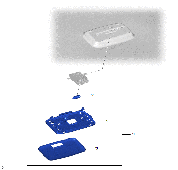
COMPONENTS
ILLUSTRATION
|
*1 |
NO. 1 ROOM LIGHT ASSEMBLY |
*2 |
NO. 2 ROOM LIGHT BULB |
|
*3 |
ROOM LIGHT LENS |
*4 |
ROOM LIGHT HOUSING |
Removal
REMOVAL
PROCEDURE
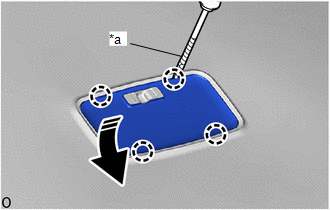
1. REMOVE NO. 1 ROOM LIGHT ASSEMBLY
(a) Using a screwdriver with its tip wrapped in protective tape, disengage the claws to remove the room light lens as shown in the illustration.
|
*a |
Protective Tape |
.png) |
Remove in this Direction |
|
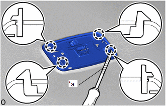
(b) Using a screwdriver with its tip wrapped in protective tape, disengage the claws to remove the room light housing from the roof headlining. |
|
|
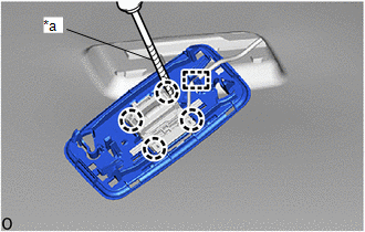
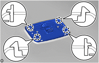
(c) Using a screwdriver with its tip wrapped in protective tape, disengage the claws and guide to remove the room light housing from the room light switch base. |
|
2. REMOVE NO. 2 ROOM LIGHT BULB
(a) Remove the No. 2 room light bulb as shown in the illustration.
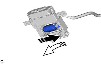
|
|
Remove in this Direction (1) |
.png) |
Remove in this Direction (2) |
Installation
INSTALLATION
PROCEDURE
1. INSTALL NO. 2 ROOM LIGHT BULB
(a) Install the No. 2 room light bulb as shown in the illustration.
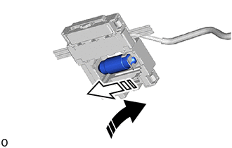
.png) |
Install in this Direction (1) |
.png) |
Install in this Direction (2) |
2. INSTALL NO. 1 ROOM LIGHT ASSEMBLY
|
(a) Engage the guide and claws to install the room light housing to the room light switch base. |
|

|
(b) Engage the claws to install the room light housing to the roof headlining. |
|
(c) Engage the claws to install the room light lens as shown in the illustration.
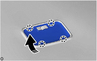
|
|
Install in this Direction |
 Installation
INSTALLATION
CAUTION / NOTICE / HINT
HINT:
Use the same procedure for the LH and RH sides.
The procedure described below is for the LH side.
PROCEDURE
1. INSTALL REAR DOOR COURT ...
 Room Light Bulb
Replacement
REPLACEMENT
PROCEDURE
1. REMOVE NO. 2 ROOM LIGHT BULB
(a) Using a screwdriver with its tip wrapped in protective tape, disengage the
claws to remove the room light lens as shown in ...
Other materials:
Toyota CH-R Service Manual > Rear View Monitor System: How To Proceed With Troubleshooting
CAUTION / NOTICE / HINT
HINT:
Use the following procedure to troubleshoot the rear view monitor system.
*: Use the Techstream.
PROCEDURE
1.
VEHICLE BROUGHT TO WORKSHOP
NEXT
...
Toyota CH-R Service Manual > Fuel Lid Opener Switch: Removal
REMOVAL
PROCEDURE
1. REMOVE FRONT DOOR SCUFF PLATE LH
Click here
2. REMOVE COWL SIDE TRIM BOARD LH
Click here
3. REMOVE NO. 1 INSTRUMENT PANEL UNDER COVER SUB-ASSEMBLY
Click here
4. REMOVE INSTRUMENT CLUSTER FINISH PANEL GARNISH ASSEMBLY
Click here
5. REMOVE INSTRUM ...
Toyota C-HR (AX20) 2023-2026 Owner's Manual
Toyota CH-R Owners Manual
- For safety and security
- Instrument cluster
- Operation of each component
- Driving
- Interior features
- Maintenance and care
- When trouble arises
- Vehicle specifications
- For owners
Toyota CH-R Service Manual
- Introduction
- Maintenance
- Audio / Video
- Cellular Communication
- Navigation / Multi Info Display
- Park Assist / Monitoring
- Brake (front)
- Brake (rear)
- Brake Control / Dynamic Control Systems
- Brake System (other)
- Parking Brake
- Axle And Differential
- Drive Shaft / Propeller Shaft
- K114 Cvt
- 3zr-fae Battery / Charging
- Networking
- Power Distribution
- Power Assist Systems
- Steering Column
- Steering Gear / Linkage
- Alignment / Handling Diagnosis
- Front Suspension
- Rear Suspension
- Tire / Wheel
- Tire Pressure Monitoring
- Door / Hatch
- Exterior Panels / Trim
- Horn
- Lighting (ext)
- Mirror (ext)
- Window / Glass
- Wiper / Washer
- Door Lock
- Heating / Air Conditioning
- Interior Panels / Trim
- Lighting (int)
- Meter / Gauge / Display
- Mirror (int)
- Power Outlets (int)
- Pre-collision
- Seat
- Seat Belt
- Supplemental Restraint Systems
- Theft Deterrent / Keyless Entry

0.0111