Toyota CH-R Service Manual: Disassembly
DISASSEMBLY
PROCEDURE
1. PRECAUTION
NOTICE:
Make sure to perform initialization after replacing the air conditioning radiator damper servo sub-assembly. If initialization is not performed, the air conditioner unit assembly will not perform properly as the air conditioning amplifier assembly will not be able to recognize the position of the air conditioning radiator damper sub-assembly.
2. REMOVE NO. 2 AIR DUCT
|
(a) Remove the screw. |
|
(b) Disengage the claws to remove the No. 2 air duct.
3. REMOVE AIR CONDITIONING DUCT SUB-ASSEMBLY
|
(a) Disengage the claws to remove the air conditioning duct sub-assembly. |
|
4. REMOVE NO. 3 INSTRUMENT PANEL WIRE
|
(a) Disconnect the 2 connectors. |
|
(b) Disengage the clamps to remove the No. 3 instrument panel wire.
5. REMOVE BLOWER ASSEMBLY
Click here
.gif)
6. REMOVE NO. 2 HEATER COVER
(a) Remove the screw.
|
(b) Disengage the claw and guide to remove the No. 2 heater cover. |
|
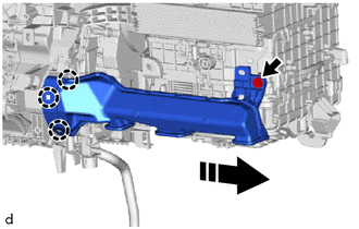
7. REMOVE QUICK HEATER ASSEMBLY
(a) Disengage the guide to remove the quick heater assembly as shown in the illustration.
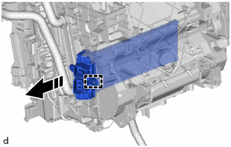
.png) |
Remove in this Direction |
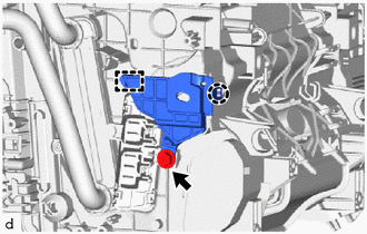
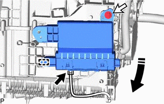
8. REMOVE AIR CONDITIONING AMPLIFIER ASSEMBLY
(a) Disconnect the connector.
|
|
Remove in this Direction |
(b) Remove the screw.
(c) Disengage the guide to remove the air conditioning amplifier assembly as shown in the illustration.
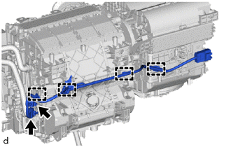
9. REMOVE AIR CONDITIONING HARNESS ASSEMBLY
|
(a) Disconnect each connector. |
|
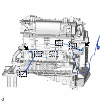
(b) Disengage clamps to remove the air conditioning harness assembly.
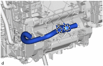
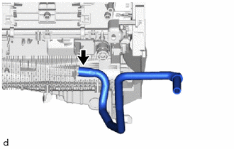
10. REMOVE DRAIN COOLER HOSE
|
(a) Remove the drain cooler hose. |
|
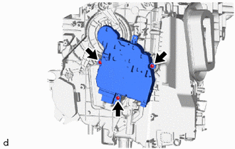
11. REMOVE NO. 1 AIR CONDITIONING RADIATOR DAMPER SERVO SUB-ASSEMBLY
|
(a) Remove the 3 screws and No. 1 air conditioning radiator damper servo sub-assembly. |
|
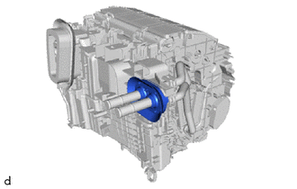
12. REMOVE HEATER PIPE GROMMET
|
(a) Remove the heater pipe grommet. |
|
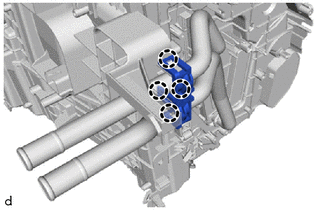
13. REMOVE HEATER CLAMP
|
(a) Disengage the claws to remove the heater clamp. |
|
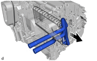
14. REMOVE HEATER RADIATOR UNIT SUB-ASSEMBLY
|
|
Remove in this Direction |
(a) Remove the heater radiator unit sub-assembly as shown in the illustration.
NOTICE:
Prepare a drain pan or cloth in case the coolant leaks.
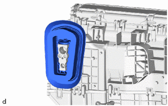
15. REMOVE COOLER EXPANSION VALVE
|
(a) Remove the grommet. |
|
|
(b) Using a 4 mm hexagon socket wrench, remove the 2 hexagon bolts and cooler expansion valve. |
|
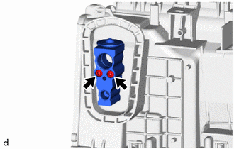
(c) Remove the 2 O-rings from the No. 1 cooler evaporator sub-assembly.
16. REMOVE NO. 1 COOLER EVAPORATOR SUB-ASSEMBLY
(a) Remove the 2 screws.
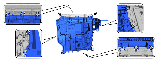
(b) Disengage the claws to remove the upper heater case with No. 1 cooler evaporator sub-assembly from the lower heater case.
|
(c) Disengage the clamp. |
|
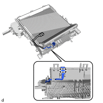
(d) Remove the No. 1 cooler evaporator sub-assembly with the No. 1 cooler thermistor from the upper heater case.
17. REMOVE NO. 1 COOLER THERMISTOR
Click here
 Components
COMPONENTS
ILLUSTRATION
*1
COWL BODY MOUNTING REINFORCEMENT LH
*2
COWL BODY MOUNTING REINFORCEMENT RH
*3
NO. 1 HEATER AIR DU ...
 Removal
REMOVAL
CAUTION / NOTICE / HINT
The necessary procedures (adjustment, calibration, initialization or registration)
that must be performed after parts are removed and installed, or replaced during ...
Other materials:
Toyota CH-R Service Manual > Airbag System: Short in Driver Side Knee Airbag Squib Circuit (B1860/64-B1863/64)
DESCRIPTION
The driver side knee airbag squib circuit consists of the airbag sensor assembly
and lower No. 1 instrument panel airbag assembly.
The airbag sensor assembly uses this circuit to deploy the airbag when deployment
conditions are met.
These DTCs are stored when a malfunction is dete ...
Toyota CH-R Service Manual > Smart Key System(for Start Function): Power Source Mode does not Change to ON (ACC)
DESCRIPTION
If the engine switch is pressed with the electrical key transmitter sub-assembly
in the cabin, the certification ECU (smart key ECU assembly) receives a signal and
changes the power source mode.
Related Data List and Active Test Items
Problem Symptom
Data Lis ...
Toyota C-HR (AX20) 2023-2026 Owner's Manual
Toyota CH-R Owners Manual
- For safety and security
- Instrument cluster
- Operation of each component
- Driving
- Interior features
- Maintenance and care
- When trouble arises
- Vehicle specifications
- For owners
Toyota CH-R Service Manual
- Introduction
- Maintenance
- Audio / Video
- Cellular Communication
- Navigation / Multi Info Display
- Park Assist / Monitoring
- Brake (front)
- Brake (rear)
- Brake Control / Dynamic Control Systems
- Brake System (other)
- Parking Brake
- Axle And Differential
- Drive Shaft / Propeller Shaft
- K114 Cvt
- 3zr-fae Battery / Charging
- Networking
- Power Distribution
- Power Assist Systems
- Steering Column
- Steering Gear / Linkage
- Alignment / Handling Diagnosis
- Front Suspension
- Rear Suspension
- Tire / Wheel
- Tire Pressure Monitoring
- Door / Hatch
- Exterior Panels / Trim
- Horn
- Lighting (ext)
- Mirror (ext)
- Window / Glass
- Wiper / Washer
- Door Lock
- Heating / Air Conditioning
- Interior Panels / Trim
- Lighting (int)
- Meter / Gauge / Display
- Mirror (int)
- Power Outlets (int)
- Pre-collision
- Seat
- Seat Belt
- Supplemental Restraint Systems
- Theft Deterrent / Keyless Entry

0.0074