Toyota CH-R Service Manual: Removal
REMOVAL
CAUTION / NOTICE / HINT
The necessary procedures (adjustment, calibration, initialization or registration) that must be performed after parts are removed and installed, or replaced during air conditioning unit removal/installation are shown below.
Necessary Procedure After Parts Removed/Installed/Replaced|
Replacement Part or Procedure |
Necessary Procedure |
Effect/Inoperative when not Performed |
Link |
|---|---|---|---|
|
Disconnect cable from negative battery terminal |
Memorize steering angle neutral point |
Lane departure alert system (w/ Steering Control) |
|
|
Pre-collision system |
|||
|
Initialize back door lock |
Power door lock control system |
|
|
|
Initialize servo motor (Air conditioning system) |
DTCs are stored |
|
PROCEDURE
1. RECOVER REFRIGERANT FROM REFRIGERATION SYSTEM
Click here
.gif)
2. DRAIN ENGINE COOLANT
Click here
3. REMOVE WINDSHIELD WIPER MOTOR AND LINK ASSEMBLY
Click here
4. REMOVE NO. 1 HEATER AIR DUCT SPLASH SHIELD SEAL
Click here
5. REMOVE WATER GUARD PLATE LH
Click here
6. REMOVE COWL BODY MOUNTING REINFORCEMENT LH
Click here
7. REMOVE COWL BODY MOUNTING REINFORCEMENT RH
Click here
8. REMOVE OUTER COWL TOP PANEL SUB-ASSEMBLY
Click here
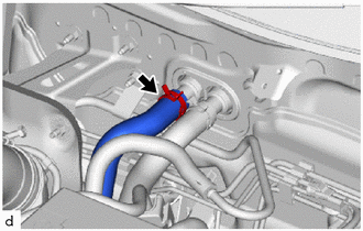
9. DISCONNECT OUTLET HEATER WATER HOSE
|
(a) Slide the hose clip to disconnect the outlet heater water hose. NOTICE:
|
|
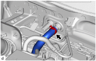
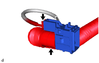
10. DISCONNECT INLET HEATER WATER HOSE
|
(a) Slide the hose clip to disconnect the inlet heater water hose. NOTICE:
|
|
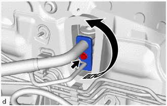
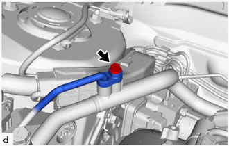
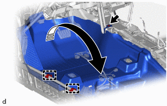
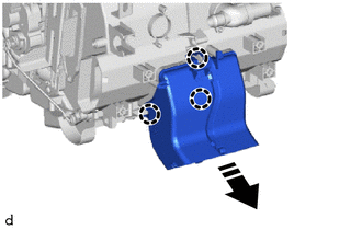
11. DISCONNECT SUCTION PIPE SUB-ASSEMBLY
(a) Remove the bolt and rotate the hook connector as shown in the illustration.
.png) |
Remove in this Direction |
|
(b) Disconnect the suction pipe sub-assembly. |
|
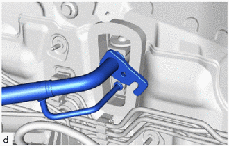
(c) Remove the 2 O-ring from the suction pipe subassembly.
NOTICE:
Seal the openings of the disconnected parts using vinyl tape to prevent entry of moisture and foreign matter.
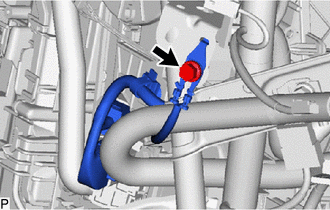
12. DISCONNECT COOLER REFRIGERANT LIQUID PIPE A
|
(a) Remove the bolt and the cooler refrigerant liquid pipe A. |
|
(b) Remove the O-ring from the cooler refrigerant liquid pipe A.
NOTICE:
Seal the openings of the disconnected parts using vinyl tape to prevent entry of moisture and foreign matter.
13. REMOVE FRONT SEAT ASSEMBLY LH
Click here
14. INSTALL FRONT SEAT ASSEMBLY RH
HINT:
Use the same procedure as for the LH side.
15. REMOVE INSTRUMENT PANEL SAFETY PAD SUB-ASSEMBLY
Click here
16. REMOVE STEERING COLUMN ASSEMBLY
Click here
17. REMOVE WINDSHIELD WIPER RELAY ASSEMBLY
Click here
18. REMOVE ECU INTEGRATION BOX RH
Click here
19. REMOVE COOLER THERMISTOR (ROOM TEMPERATURE SENSOR)
|
(a) Disconnect the connector and aspirator to remove the cooler thermistor (room temperature sensor). |
|
20. REMOVE NO. 3 DASH PANEL INSULATOR PAD
|
(a) Remove the 2 front floor carpet clips. |
|
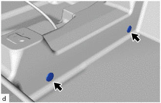
(b) Remove the clip.
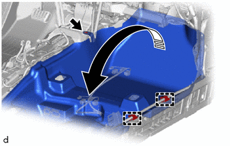
|
|
Remove in this Direction |
(c) Disengage the clamps to turn back the front floor carpet assembly as shown in the illustration.
|
(d) Disengage the clips to remove the No. 3 dash panel insulator pad. |
|
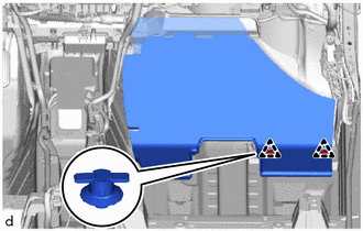
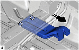
21. REMOVE REAR NO. 6 AIR DUCT
(a) Disengage the claws to remove the rear No. 6 air duct as shown in the illustration.
|
|
Remove in this Direction |
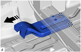
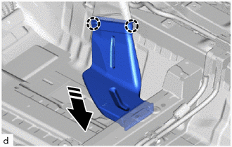
22. REMOVE REAR NO. 5 AIR DUCT
|
|
Remove in this Direction |
(a) Disengage the claws to remove the rear No. 5 air duct as shown in the illustration.
23. REMOVE REAR NO. 4 AIR DUCT
|
(a) Remove the 2 front floor carpet clips. |
|
(b) Remove the clip.
|
|
Remove in this Direction |
(c) Disengage the clamps to turn back the front floor carpet assembly as shown in the illustration.
(d) Disengage the claws to remove the rear No. 4 air duct as shown in the illustration.
|
|
Remove in this Direction |
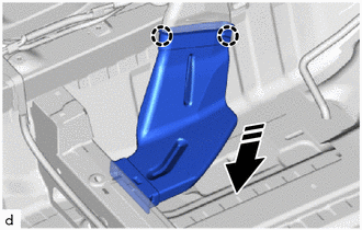
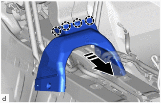
24. REMOVE REAR NO. 3 AIR DUCT
(a) Disengage the claws to remove the rear No. 3 air duct as shown in the illustration.
|
|
Remove in this Direction |
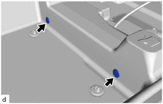
25. REMOVE REAR NO. 2 AIR DUCT
|
|
Remove in this Direction |
(a) Disengage the claws to remove the rear No. 2 air duct.
26. REMOVE REAR NO. 1 AIR DUCT
|
(a) Disengage the claws to remove the rear No. 1 air duct. |
|
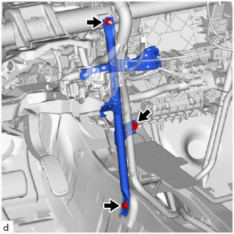
27. REMOVE NO. 1 INSTRUMENT PANEL BRACE SUB-ASSEMBLY
|
(a) Remove the bolt to disconnect the ground wire. |
|
|
(b) Remove the 2 nuts and separate the relay block assembly. |
|
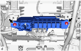
|
(c) Disengage the clamps to disconnect the wire harness. |
|
|
(d) Remove the bolt, screw, nut and the No. 1 instrument panel brace sub-assembly. |
|
28. REMOVE NO. 2 INSTRUMENT PANEL BRACE SUB-ASSEMBLY
|
(a) Remove the bolt to disconnect the ground wire. |
|
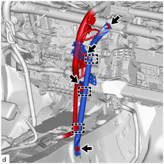
(b) Disengage the clamps to disconnect the wire harness.
(c) Remove the bolt, screw, nut and the No. 2 instrument panel brace sub-assembly.
29. REMOVE NO. 3 INSTRUMENT PANEL TO COWL BRACE SUB-ASSEMBLY
|
(a) Disengage the clamp and claws. |
|
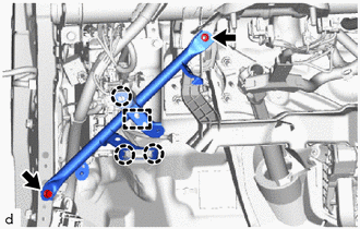
(b) Remove the bolt, nut and the No. 3 instrument panel to cowl brace sub-assembly.
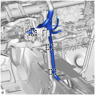
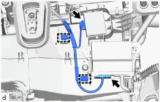
30. DISCONNECT INSTRUMENT PANEL WIRE
(a) Disconnect each connector.
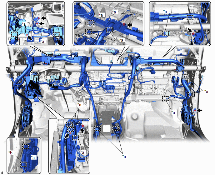
|
*a |
Clamp |
*b |
Hook |
(b) Remove the bolt and screw.
(c) Remove the 4 bolts to disconnect the 4 ground wires.
(d) Remove the bolt and nut to separate the instrument panel junction block assembly with main body ECU.
(e) Disengage clamps and hook to disconnect the instrument panel wire.
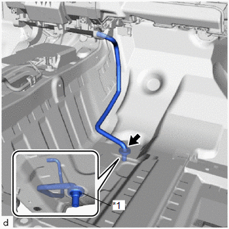
31. DISCONNECT DRAIN COOLER HOSE
|
(a) Disconnect the drain cooler hose. NOTICE: If the cooler unit drain hose grommet is disconnected from the vehicle body while disconnecting the drain cooler hose, make sure to replace it with a new one. Failure to do so may cause water ingress. |
|
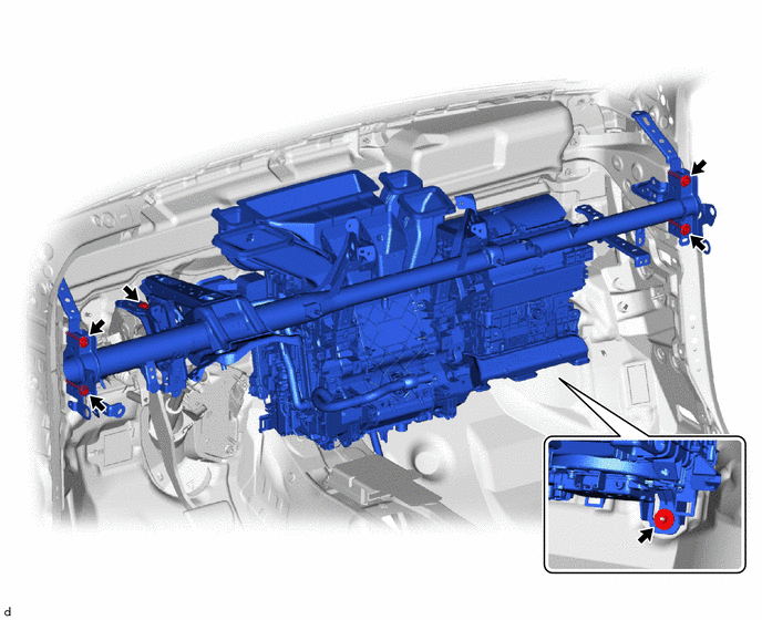
32. REMOVE INSTRUMENT PANEL REINFORCEMENT ASSEMBLY WITH AIR CONDITIONER UNIT ASSEMBLY
NOTICE:
- Be sure to support the air conditioner unit assembly when removing it. Failure to do so may cause the bracket of the air conditioner unit assembly to break.
- When disassembling the air conditioner unit assembly, eliminate static electricity by touching the vehicle body to prevent the components from being damaged.
|
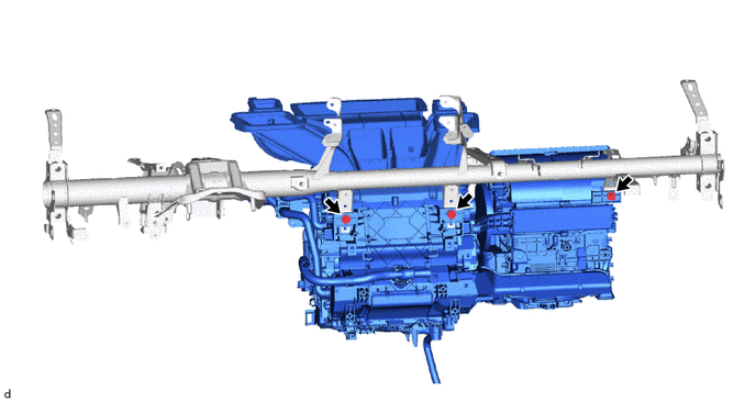
(a) Remove the 2 bolts. |
|
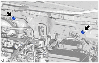
(b) Remove the 5 bolts.
(c) Remove the nut.
|
(d) Disengage the clamps. |
|
(e) Disconnect 2 connectors.
(f) Disengage the guides to remove the instrument panel reinforcement assembly with air conditioner unit assembly as shown in the illustration.
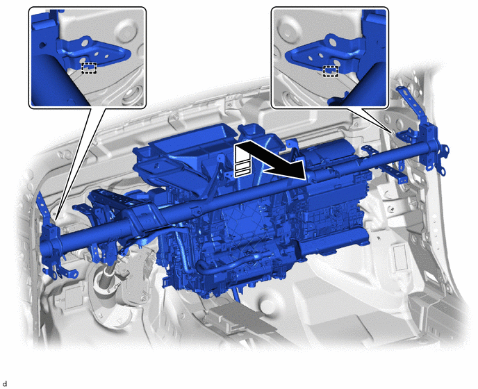
|
|
Remove in this Direction |
- |
- |
33. REMOVE AIR CONDITIONER UNIT ASSEMBLY
(a) Remove the 3 bolts and air conditioner unit assembly from the instrument panel reinforcement assembly.
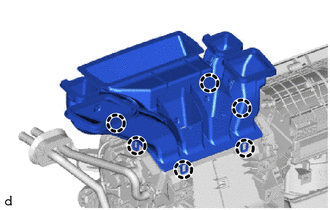
34. REMOVE LOWER DEFROSTER NOZZLE ASSEMBLY
|
(a) Disengage the 6 claws to remove the lower defroster nozzle assembly. |
|
 Disassembly
DISASSEMBLY
PROCEDURE
1. PRECAUTION
NOTICE:
Make sure to perform initialization after replacing the air conditioning radiator
damper servo sub-assembly. If initialization is not performed, the a ...
 Reassembly
REASSEMBLY
PROCEDURE
1. INSTALL NO. 1 COOLER THERMISTOR
Click here
2. INSTALL NO. 1 COOLER EVAPORATOR SUB-ASSEMBLY
(a) Install the No. 1 cooler evaporator sub-assembly with the No. ...
Other materials:
Toyota CH-R Service Manual > General Maintenance: Engine
ENGINE
HINT:
Perform these procedures after the engine has cooled down.
INSPECT DRIVE BELT
(a) Check the drive belt.
Click here
INSPECT ENGINE OIL AND OIL FILTER
(a) Check the engine oil and oil filter.
Click here
INSPECT ENGINE COOLANT
(a) Check the engine coolant.
Click here
...
Toyota CH-R Service Manual > Air Conditioning System(for Automatic Air Conditioning System With Top-mounted
Air Conditioner Pressure Sensor): Room Temperature Sensor Circuit (B1411)
DESCRIPTION
The cooler thermistor (room temperature sensor) is installed in the instrument
panel to detect the cabin temperature, which is used to control the air conditioning
system. The resistance of the cooler thermistor (room temperature sensor) changes
in accordance with the cabin temper ...
Toyota C-HR (AX20) 2023-2026 Owner's Manual
Toyota CH-R Owners Manual
- For safety and security
- Instrument cluster
- Operation of each component
- Driving
- Interior features
- Maintenance and care
- When trouble arises
- Vehicle specifications
- For owners
Toyota CH-R Service Manual
- Introduction
- Maintenance
- Audio / Video
- Cellular Communication
- Navigation / Multi Info Display
- Park Assist / Monitoring
- Brake (front)
- Brake (rear)
- Brake Control / Dynamic Control Systems
- Brake System (other)
- Parking Brake
- Axle And Differential
- Drive Shaft / Propeller Shaft
- K114 Cvt
- 3zr-fae Battery / Charging
- Networking
- Power Distribution
- Power Assist Systems
- Steering Column
- Steering Gear / Linkage
- Alignment / Handling Diagnosis
- Front Suspension
- Rear Suspension
- Tire / Wheel
- Tire Pressure Monitoring
- Door / Hatch
- Exterior Panels / Trim
- Horn
- Lighting (ext)
- Mirror (ext)
- Window / Glass
- Wiper / Washer
- Door Lock
- Heating / Air Conditioning
- Interior Panels / Trim
- Lighting (int)
- Meter / Gauge / Display
- Mirror (int)
- Power Outlets (int)
- Pre-collision
- Seat
- Seat Belt
- Supplemental Restraint Systems
- Theft Deterrent / Keyless Entry

0.0091