Toyota CH-R Service Manual: Reassembly
REASSEMBLY
PROCEDURE
1. INSTALL NO. 1 COOLER THERMISTOR
Click here
.gif)
2. INSTALL NO. 1 COOLER EVAPORATOR SUB-ASSEMBLY
|
(a) Install the No. 1 cooler evaporator sub-assembly with the No. 1 cooler thermistor to the upper heater case. |
|
.png)
(b) Engage the clamp.
(c) Engage the claws to install the upper heater case with the No. 1 cooler evaporator sub-assembly to the lower heater case.
.png)
(d) Install the 2 screws.
3. INSTALL COOLER EXPANSION VALVE
(a) Sufficiently apply compressor oil to 2 new O-rings and the fitting surfaces of the No. 1 cooler evaporator sub-assembly.
Compressor Oil:
ND-OIL 12 or equivalent
(b) Install the 2 O-rings to the No. 1 cooler evaporator sub-assembly.
NOTICE:
Keep the O-rings and O-ring fitting surfaces free of foreign matter.
|
(c) Using a 4 mm hexagon socket wrench, install the cooler expansion valve with the 2 hexagon bolts. Torque: 3.5 N·m {36 kgf·cm, 31 in·lbf} |
|
.png)
|
(d) Install the grommet. |
|
.png)
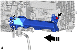
4. INSTALL HEATER RADIATOR UNIT SUB-ASSEMBLY
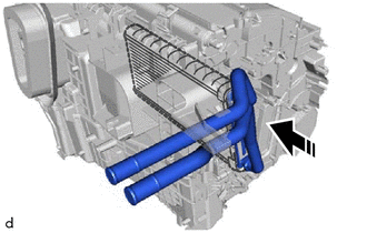
.png) |
Install in this Direction |
(a) Install the heater radiator unit sub-assembly as shown in the illustration.
5. INSTALL HEATER CLAMP
|
(a) Engage the claws to install the heater clamp. |
|
.png)
6. INSTALL HEATER PIPE GROMMET
|
(a) Install the heater grommet. |
|
.png)
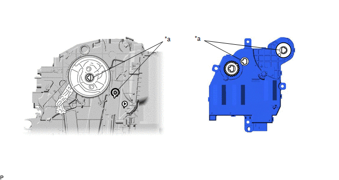
7. INSTALL NO. 1 AIR CONDITIONING RADIATOR DAMPER SERVO SUB-ASSEMBLY
(a) Align each gear on the air conditioner radiator assembly as shown in the illustration, and then check that the gears of the No. 1 air conditioning radiator damper servo sub-assembly are aligned as shown in the illustration.
|
*a |
Reference Point |
- |
- |
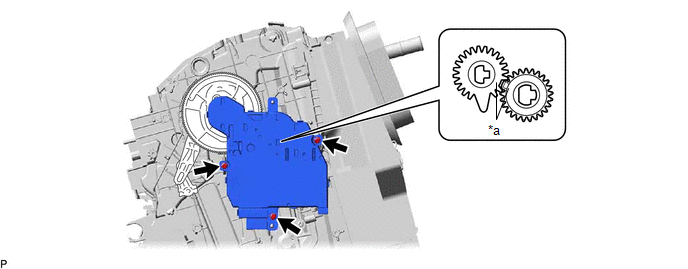
(b) Using the reference points, install the No. 1 air conditioning radiator damper servo sub-assembly with the 3 screws.
|
*a |
Reference Point |
- |
- |
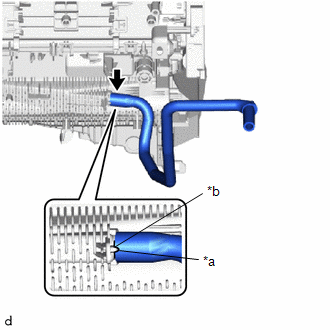
8. INSTALL DRAIN COOLER HOSE
|
(a) Align the hose notch with the rib as shown in the illustration and install the drain cooler hose. |
|
9. INSTALL AIR CONDITIONING HARNESS ASSEMBLY
|
(a) Engage the clamps. |
|
.png)
(b) Connect each connector to install the air conditioning harness assembly.
10. INSTALL AIR CONDITIONING AMPLIFIER ASSEMBLY
(a) Engage the guide to temporarily install the air conditioning amplifier assembly as shown in the illustration.
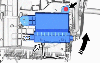
|
|
Install in this Direction |
(b) Install the air conditioning amplifier assembly with the screw.
(c) Connect the connector.
11. INSTALL QUICK HEATER ASSEMBLY
(a) Engage the guide to install the quick heater assembly as shown in the illustration.
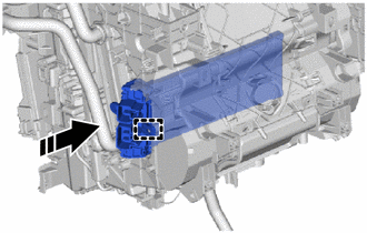
|
|
Install in this Direction |
12. INSTALL NO. 2 HEATER COVER
|
(a) Engage the claw and guide to install the No. 2 heater cover. |
|
.png)
(b) Install the screw.
13. INSTALL BLOWER ASSEMBLY
Click here
14. INSTALL NO. 3 INSTRUMENT PANEL WIRE
|
(a) Engage the clamps to install the No. 3 instrument panel wire. |
|
.png)
(b) Connect the 2 connectors.
15. INSTALL AIR CONDITIONING DUCT SUB-ASSEMBLY
|
(a) Engage the claws to install the air conditioning duct sub-assembly. |
|
.png)
16. INSTALL NO. 2 AIR DUCT
|
(a) Engage the claws to remove the No. 2 air duct. |
|
(b) Install the screw.
 Removal
REMOVAL
CAUTION / NOTICE / HINT
The necessary procedures (adjustment, calibration, initialization or registration)
that must be performed after parts are removed and installed, or replaced during ...
 Installation
INSTALLATION
PROCEDURE
1. INSTALL LOWER DEFROSTER NOZZLE ASSEMBLY
(a) Engage the claws to install the lower defroster nozzle assembly.
2. ...
Other materials:
Toyota CH-R Service Manual > Automatic High Beam System: Automatic High Beam Switch Circuit
DESCRIPTION
The main body ECU (multiplex network body ECU) detects auto high beam switch
signals. The automatic high beam system can be turned on and off by operating the
integration control and panel assembly (automatic high beam switch).
WIRING DIAGRAM
CAUTION / NOTICE / HINT
NOTICE:
Be ...
Toyota CH-R Service Manual > Immobiliser System(w/ Smart Key System): Engine Starter Communication Malfunction (B2779)
DESCRIPTION
If the remote engine start ECU does not respond to the certification ECU (smart
key ECU assembly) or the remote engine start ID is not registered, this DTC is stored.
HINT:
Registration status of the remote engine start ECU ID can be checked using the
"Wireless C Code" i ...
Toyota C-HR (AX20) 2023-2026 Owner's Manual
Toyota CH-R Owners Manual
- For safety and security
- Instrument cluster
- Operation of each component
- Driving
- Interior features
- Maintenance and care
- When trouble arises
- Vehicle specifications
- For owners
Toyota CH-R Service Manual
- Introduction
- Maintenance
- Audio / Video
- Cellular Communication
- Navigation / Multi Info Display
- Park Assist / Monitoring
- Brake (front)
- Brake (rear)
- Brake Control / Dynamic Control Systems
- Brake System (other)
- Parking Brake
- Axle And Differential
- Drive Shaft / Propeller Shaft
- K114 Cvt
- 3zr-fae Battery / Charging
- Networking
- Power Distribution
- Power Assist Systems
- Steering Column
- Steering Gear / Linkage
- Alignment / Handling Diagnosis
- Front Suspension
- Rear Suspension
- Tire / Wheel
- Tire Pressure Monitoring
- Door / Hatch
- Exterior Panels / Trim
- Horn
- Lighting (ext)
- Mirror (ext)
- Window / Glass
- Wiper / Washer
- Door Lock
- Heating / Air Conditioning
- Interior Panels / Trim
- Lighting (int)
- Meter / Gauge / Display
- Mirror (int)
- Power Outlets (int)
- Pre-collision
- Seat
- Seat Belt
- Supplemental Restraint Systems
- Theft Deterrent / Keyless Entry

0.0102