Toyota CH-R Service Manual: Installation
INSTALLATION
PROCEDURE
1. INSTALL LOWER DEFROSTER NOZZLE ASSEMBLY
|
(a) Engage the claws to install the lower defroster nozzle assembly. |
|
2. TEMPORARILY INSTALL AIR CONDITIONER UNIT ASSEMBLY
(a) Temporarily install the air conditioner unit assembly to the instrument panel reinforcement assembly with the 3 bolts.
3. INSTALL INSTRUMENT PANEL REINFORCEMENT ASSEMBLY WITH AIR CONDITIONER UNIT ASSEMBLY
NOTICE:
Be sure to support the air conditioner unit assembly when installing it. Failure to do so may cause the bracket of the air conditioner unit assembly to break.
(a) Engage the guides to install the instrument panel reinforcement assembly with air conditioner unit assembly as shown in the illustration.
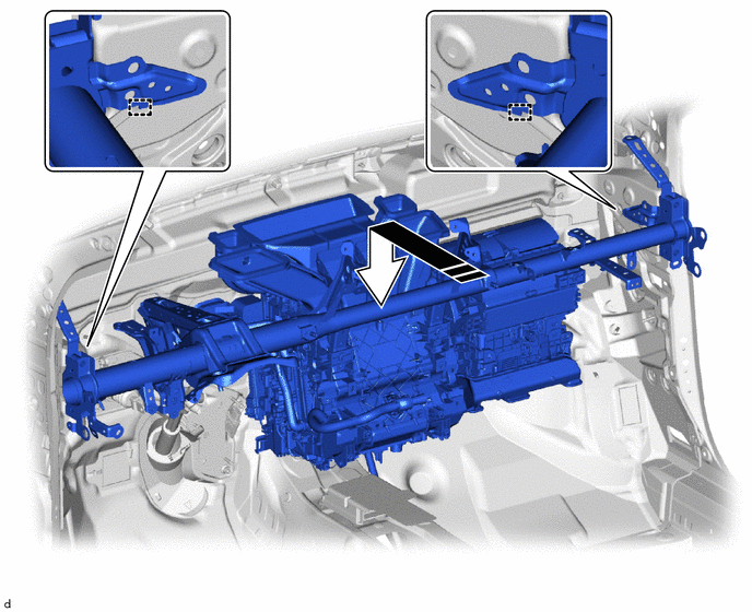
.png) |
Install in this Direction |
- |
- |
|
(b) Connect 2 connectors. |
|
.png)
(c) Engage the clamps.
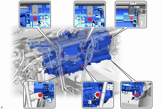
(d) Install the 5 bolts.
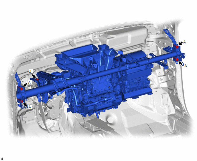
Torque:
Bolt A :
25 N·m {255 kgf·cm, 18 ft·lbf}
Bolt B :
23.6 N·m {241 kgf·cm, 17 ft·lbf}
(e) Temporarily install the nut.
(f) Install the 2 bolts.
Torque:
25 N·m {255 kgf·cm, 18 ft·lbf}
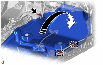
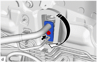
4. CONNECT DRAIN COOLER HOSE
|
(a) Connect the drain cooler hose. NOTICE: If the cooler unit drain hose grommet is disconnected from the vehicle body while connecting the drain cooler hose, make sure to replace it with a new one. Failure to do so may cause water ingress. |
|
.png)
5. INSTALL INSTRUMENT PANEL WIRE
(a) Engage clamps and hook to connect the instrument panel wire.
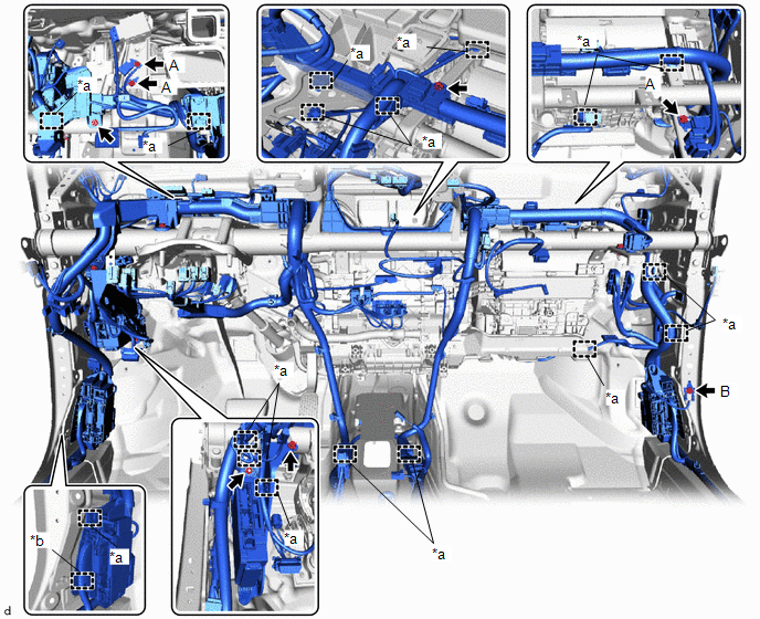
|
*a |
Clamp |
*b |
Hook |
(b) Install the instrument panel junction block assembly with main body ECU with the bolt and nut.
Torque:
8.0 N·m {82 kgf·cm, 71 in·lbf}
(c) Install the 4 ground wires with the 4 bolts.
Torque:
Bolt A :
10.5 N·m {107 kgf·cm, 8 ft·lbf}
Bolt B (Part No. 90119-06995) :
10.5 N·m {107 kgf·cm, 8 ft·lbf}
Bolt B (Part No. 90119-06915) :
8.5 N·m {87 kgf·cm, 75 in·lbf}
Bolt B (Part No. 90119-06A07) :
10 N·m {102 kgf·cm, 7 ft·lbf}
(d) Install the bolt and screw.
Torque:
Bolt :
8.0 N·m {82 kgf·cm, 71 in·lbf}
(e) Connect each connector.
6. INSTALL NO. 3 INSTRUMENT PANEL TO COWL BRACE SUB-ASSEMBLY
|
(a) Install the No. 3 instrument panel to cowl brace sub-assembly with the nut and bolt. Torque: Bolt : 10 N·m {102 kgf·cm, 7 ft·lbf} Nut : 6.0 N·m {61 kgf·cm, 53 in·lbf} |
|
.png)
(b) Engage the claws and clamps.
7. INSTALL NO. 2 INSTRUMENT PANEL BRACE SUB-ASSEMBLY
|
(a) Install the No. 2 instrument panel brace sub-assembly with the bolt and nut. Torque: Bolt : 20 N·m {204 kgf·cm, 15 ft·lbf} Nut : 18 N·m {184 kgf·cm, 13 ft·lbf} |
|
.png)
(b) Temporarily install the screw.
HINT:
Do not fully tighten the screw.
(c) Install the ground wire with the bolt.
Torque:
10.5 N·m {107 kgf·cm, 8 ft·lbf}
(d) Engage the clamps to connect the wire harness.
8. INSTALL NO. 1 INSTRUMENT PANEL BRACE SUB-ASSEMBLY
(a) Install the No. 1 instrument panel brace sub-assembly with the bolt and nut.
Torque:
Bolt :
20 N·m {204 kgf·cm, 15 ft·lbf}
Nut :
18 N·m {184 kgf·cm, 13 ft·lbf}
(b) Temporarily install the screw.
HINT:
Do not fully tighten the screw.
|
(c) Engage the clamps to connect the wire harness. |
|
.png)
(d) Install the relay block assembly with the 2 nuts.
Torque:
8.0 N·m {82 kgf·cm, 71 in·lbf}
(e) Install the bolt to connect the ground wire.
Torque:
10.5 N·m {107 kgf·cm, 8 ft·lbf}
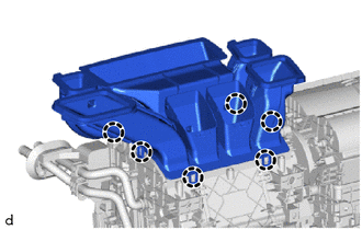
9. INSTALL AIR CONDITIONER UNIT ASSEMBLY
(a) Tighten the 3 bolts, 2 screws and nut in the order shown in the illustration to install the air conditioner unit.
Torque:
9.8 N·m {100 kgf·cm, 87 in·lbf}
10. INSTALL REAR NO. 1 AIR DUCT
(a) Engage the claws to install the rear No. 1 air duct.
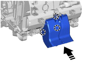
|
|
Install in this Direction |
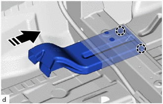
11. INSTALL REAR NO. 2 AIR DUCT
(a) Engage the claws to install the rear No. 2 air duct as shown in the illustration.
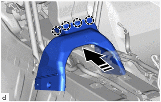
|
|
Install in this Direction |
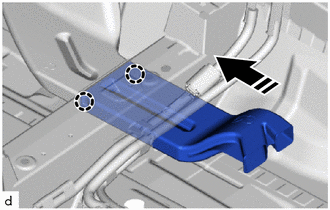
12. INSTALL REAR NO. 3 AIR DUCT
(a) Engage the claws to install the rear No. 3 air duct as shown in the illustration.
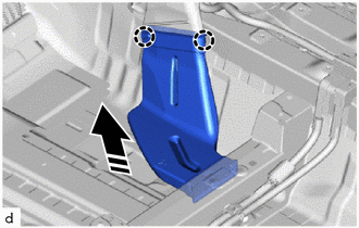
|
|
Install in this Direction |
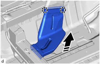
13. INSTALL REAR NO. 4 AIR DUCT
(a) Engage the claws to install the rear No. 4 air duct as shown in the illustration.
|
|
Install in this Direction |
(b) Install the front floor carpet assembly to its original position as shown in the illustration.
|
|
Install in this Direction |
(c) Engage the clamps.
(d) Install the clip.
(e) Install the 2 front floor carpet clips.
14. INSTALL REAR NO. 5 AIR DUCT
(a) Engage the claws to install the rear No. 5 air duct as shown in the illustration.
|
|
Install in this Direction |
15. INSTALL REAR NO. 6 AIR DUCT
(a) Engage the claws to install the rear No. 6 air duct as shown in the illustration.
|
|
Install in this Direction |
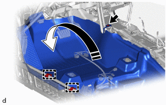
16. INSTALL NO. 3 DASH PANEL INSULATOR PAD
|
(a) Engage the clips to install the No. 3 dash panel insulator pad. |
|
.png)
(b) Install the front floor carpet assembly to its original position as shown in the illustration.
|
|
Install in this Direction |
(c) Engage the clamps.
(d) Install the clip.
(e) Install the 2 front floor carpet clips.
17. INSTALL COOLER THERMISTOR (ROOM TEMPERATURE SENSOR)
(a) Connect the aspirator and connector to install the cooler thermistor (room temperature sensor).
18. INSTALL ECU INTEGRATION BOX RH
Click here
.gif)
19. INSTALL WINDSHIELD WIPER RELAY ASSEMBLY
Click here
20. INSTALL STEERING COLUMN ASSEMBLY
Click here
21. INSTALL INSTRUMENT PANEL SAFETY PAD SUB-ASSEMBLY
Click here
22. INSTALL FRONT SEAT ASSEMBLY LH
Click here
23. INSTALL FRONT SEAT ASSEMBLY RH
HINT:
Use the same procedure as for the LH side.
24. CONNECT COOLER REFRIGERANT LIQUID PIPE A
(a) Remove the vinyl tape from the cooler refrigerant liquid pipe A.
(b) Apply sufficient compressor oil to a new O-ring and fitting surface of the cooler refrigerant liquid pipe A.
Compressor Oil:
ND-OIL 12 or equivalent
(c) Install the O-ring to the cooler refrigerant liquid pipe A.
NOTICE:
Keep the O-ring and O-ring fitting surface free of foreign matter.
(d) Install the bolt and the cooler refrigerant liquid pipe A.
25. CONNECT SUCTION PIPE SUB-ASSEMBLY
(a) Remove the vinyl tape from the suction pipe sub-assembly.
(b) Apply sufficient compressor oil to a new O-ring and fitting surface of the suction pipe sub-assembly.
Compressor Oil:
ND-OIL 12 or equivalent
(c) Install the O-ring to the suction pipe sub-assembly.
NOTICE:
Keep the O-ring and O-ring fitting surface free of foreign matter.
(d) Connect the suction pipe sub-assembly.
(e) Rotate the hook connector as shown in the illustration.
|
|
Install in this Direction |
(f) Insert the hose joint into the fitting hole securely and install the bolt.
Torque:
9.8 N·m {100 kgf·cm, 87 in·lbf}
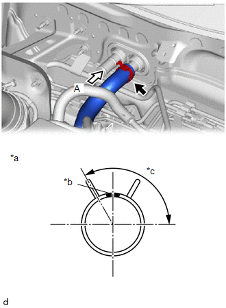
26. CONNECT INLET HEATER WATER HOSE
|
(a) Connect the inlet heater water hose with the marking (pink) facing up and engage the clip within the area shown in the illustration. NOTICE: Do not apply excessive force to the inlet heater water hose. |
|
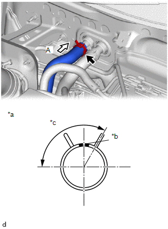
27. CONNECT OUTLET HEATER WATER HOSE
|
(a) Connect the outlet heater water hose with the marking (blue) facing up and engage the clip within the area shown in the illustration. NOTICE: Do not apply excessive force to the outlet heater water hose. |
|
28. INSTALL OUTER COWL TOP PANEL SUB-ASSEMBLY
Click here
29. INSTALL COWL BODY MOUNTING REINFORCEMENT LH
Click here
30. INSTALL COWL BODY MOUNTING REINFORCEMENT RH
Click here
31. INSTALL WATER GUARD PLATE LH
Click here
32. INSTALL NO. 1 HEATER AIR DUCT SPLASH SHIELD SEAL
Click here
33. INSTALL WINDSHIELD WIPER MOTOR AND LINK ASSEMBLY
Click here
34. ADD ENGINE COOLANT
Click here
35. INSPECT FOR COOLANT LEAK
Click here
36. CHARGE AIR CONDITIONING SYSTEM WITH REFRIGERANT
Click here
37. WARM UP ENGINE
Click here
38. INSPECT FOR REFRIGERANT LEAK
Click here
39. INITIALIZATION SERVO MOTOR
Click here
 Reassembly
REASSEMBLY
PROCEDURE
1. INSTALL NO. 1 COOLER THERMISTOR
Click here
2. INSTALL NO. 1 COOLER EVAPORATOR SUB-ASSEMBLY
(a) Install the No. 1 cooler evaporator sub-assembly with the No. ...

Other materials:
Toyota CH-R Service Manual > Meter / Gauge System: Steering Pad Switch Circuit
DESCRIPTION
The combination meter assembly and steering pad switch assembly are connected
via direct line. The main display and multi-information display in the combination
meter assembly are operated using the switches of the steering pad switch assembly.
WIRING DIAGRAM
CAUTION / NOTICE / ...
Toyota CH-R Service Manual > Immobiliser System(w/o Smart Key System): Unmatched Key Code (B2795)
DESCRIPTION
This DTC is stored when a key with a different vehicle serial number is inserted
into the ignition key cylinder.
DTC No.
Detection Item
DTC Detection Condition
Trouble Area
Note
B2795
Unmatched Key Cod ...
Toyota C-HR (AX20) 2023-2026 Owner's Manual
Toyota CH-R Owners Manual
- For safety and security
- Instrument cluster
- Operation of each component
- Driving
- Interior features
- Maintenance and care
- When trouble arises
- Vehicle specifications
- For owners
Toyota CH-R Service Manual
- Introduction
- Maintenance
- Audio / Video
- Cellular Communication
- Navigation / Multi Info Display
- Park Assist / Monitoring
- Brake (front)
- Brake (rear)
- Brake Control / Dynamic Control Systems
- Brake System (other)
- Parking Brake
- Axle And Differential
- Drive Shaft / Propeller Shaft
- K114 Cvt
- 3zr-fae Battery / Charging
- Networking
- Power Distribution
- Power Assist Systems
- Steering Column
- Steering Gear / Linkage
- Alignment / Handling Diagnosis
- Front Suspension
- Rear Suspension
- Tire / Wheel
- Tire Pressure Monitoring
- Door / Hatch
- Exterior Panels / Trim
- Horn
- Lighting (ext)
- Mirror (ext)
- Window / Glass
- Wiper / Washer
- Door Lock
- Heating / Air Conditioning
- Interior Panels / Trim
- Lighting (int)
- Meter / Gauge / Display
- Mirror (int)
- Power Outlets (int)
- Pre-collision
- Seat
- Seat Belt
- Supplemental Restraint Systems
- Theft Deterrent / Keyless Entry

0.0087