Toyota CH-R Service Manual: Parts Location
PARTS LOCATION
ILLUSTRATION
|
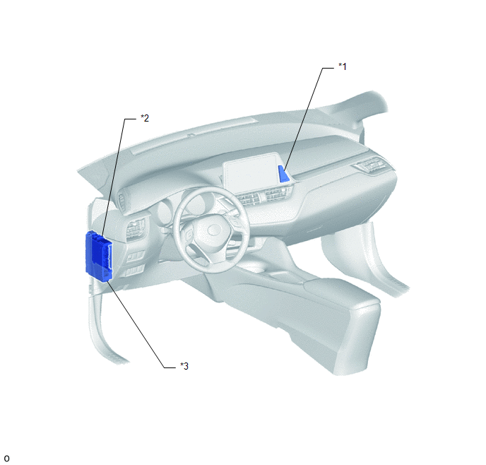
*1 |
CLOCK ASSEMBLY |
*2 |
MAIN BODY ECU (MULTIPLEX NETWORK BODY ECU) |
|
*3 |
INSTRUMENT PANEL JUNCTION BLOCK ASSEMBLY - ECU-DCC NO. 2 FUSE - ECU-ACC FUSE - PANEL FUSE - ECU-IG1 NO. 4 FUSE - ACC RELAY - TAIL RELAY |
- |
- |
 Clock System
...
 System Diagram
SYSTEM DIAGRAM
...
Other materials:
Toyota CH-R Service Manual > Occupant Classification System: Terminals Of Ecu
TERMINALS OF ECU
OCCUPANT DETECTION ECU
Terminal No. (Symbol)
Wiring Color
Terminal Description
Condition
Specified Condition
Y5-1 (SVC1) - Y5-5 (SGD1)
R - G
Front in weight detection sensor sub-assembl ...
Toyota CH-R Service Manual > Lighting (ext): High Mounted Stop Light Assembly
Components
COMPONENTS
ILLUSTRATION
*1
CENTER STOP LIGHT ASSEMBLY
*2
NO. 2 REAR SPOILER COVER
Removal
REMOVAL
PROCEDURE
1. REMOVE REAR SPOILER ASSEMBLY
Click here
2. REMOVE NO. 2 REAR SPOILER COVER
Click here
3. REMOVE CENT ...
Toyota C-HR (AX20) 2023-2026 Owner's Manual
Toyota CH-R Owners Manual
- For safety and security
- Instrument cluster
- Operation of each component
- Driving
- Interior features
- Maintenance and care
- When trouble arises
- Vehicle specifications
- For owners
Toyota CH-R Service Manual
- Introduction
- Maintenance
- Audio / Video
- Cellular Communication
- Navigation / Multi Info Display
- Park Assist / Monitoring
- Brake (front)
- Brake (rear)
- Brake Control / Dynamic Control Systems
- Brake System (other)
- Parking Brake
- Axle And Differential
- Drive Shaft / Propeller Shaft
- K114 Cvt
- 3zr-fae Battery / Charging
- Networking
- Power Distribution
- Power Assist Systems
- Steering Column
- Steering Gear / Linkage
- Alignment / Handling Diagnosis
- Front Suspension
- Rear Suspension
- Tire / Wheel
- Tire Pressure Monitoring
- Door / Hatch
- Exterior Panels / Trim
- Horn
- Lighting (ext)
- Mirror (ext)
- Window / Glass
- Wiper / Washer
- Door Lock
- Heating / Air Conditioning
- Interior Panels / Trim
- Lighting (int)
- Meter / Gauge / Display
- Mirror (int)
- Power Outlets (int)
- Pre-collision
- Seat
- Seat Belt
- Supplemental Restraint Systems
- Theft Deterrent / Keyless Entry

0.0112