Toyota CH-R Service Manual: Speedometer Malfunction
DESCRIPTION
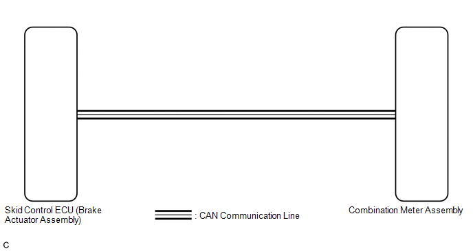
The combination meter assembly receives vehicle speed signals from the skid control ECU (brake actuator assembly) via CAN communication. The speed sensor detects the wheel speed and sends the appropriate signals to the skid control ECU (brake actuator assembly). The skid control ECU (brake actuator assembly) supplies power to the vehicle speed sensor. The skid control ECU (brake actuator assembly) detects vehicle speed signals based on pulses of the voltage.
HINT:
- Factors that affect the indicated vehicle speed include the tire size,
tire inflation, and tire wear. The speed indicated on the speedometer has
an allowable margin of error. This can be tested using the Techstream. For
details about testing and the margin of error, see the reference chart.
Click here
.gif)
- If the vehicle speed sensor circuit has a malfunction, the skid control
ECU (brake actuator assembly) stores DTCs. Troubleshoot the vehicle stability
control system.
Click here
WIRING DIAGRAM
CAUTION / NOTICE / HINT
NOTICE:
- If the vehicle speed is outside the allowable range when tested, perform
the on-vehicle inspection.
Click here
- When replacing the combination meter assembly, always replace it with a new one. If a combination meter assembly which was installed to another vehicle is used, the information stored in it will not match the information from the vehicle and a DTC may be stored.
HINT:
Before starting the following inspection, check tire size and tire air pressure.
PROCEDURE
|
1. |
CHECK FOR DTC (METER / GAUGE SYSTEM) |
(a) Check if meter / gauge system DTCs are output
Click here
|
Result |
Proceed to |
|---|---|
|
Meter / gauge system DTCs are not output. |
A |
|
Meter / gauge system DTCs are output. |
B |
| B | .gif) |
GO TO DIAGNOSTIC TROUBLE CODE CHART |
|
.gif)
|
2. |
CHECK FOR DTC (VEHICLE STABILITY CONTROL SYSTEM) |
(a) Check if vehicle stability control system DTCs are output.
Click here
|
Result |
Proceed to |
|---|---|
|
Vehicle stability control system DTCs are not output. |
A |
|
Vehicle stability control system DTCs are output. |
B |
| B | |
GO TO DIAGNOSTIC TROUBLE CODE CHART |
|
|
3. |
PERFORM ACTIVE TEST USING TECHSTREAM (SPEED METER OPERATION) |
(a) Connect the Techstream to the DLC3.
(b) Turn the ignition switch to ON.
(c) Turn the Techstream on.
(d) Enter the following menus: Body Electrical / Combination Meter / Active Test.
(e) Perform the Active Test according to the display on the Techstream.
Body Electrical > Combination Meter > Active Test|
Tester Display |
Measurement Item |
Control Range |
Diagnostic Note |
|---|---|---|---|
|
Speed Meter Operation |
Speedometer |
OFF, 0, 40, 80, 120, 160, 200, 240, 280 |
There is a deviation in the values displayed on the speedometer (Control range → Speedometer display)
(1)for Gauge speedometer*1 Reference km/h:
(2) for Gauge speedometer*2 Reference km/h:
(3) for Gauge speedometer*3 Reference mph:
|
- *1: w/o Occupant Classification System
- *2: w/ Occupant Classification System and w/o Daytime Running Light OFF function
- *3: w/ Occupant Classification System and w/ Daytime Running Light OFF function
|
Tester Display |
|---|
|
Speed Meter Operation |
OK:
Speedometer indication is normal.
| OK | |
REPLACE SKID CONTROL ECU (BRAKE ACTUATOR ASSEMBLY) |
| NG | |
REPLACE COMBINATION METER ASSEMBLY |
 Entire Combination Meter does not Operate
DESCRIPTION
This circuit is the power source circuit for the combination meter assembly.
This circuit provides two types of power sources; one is a constant power source,
and the other is an IG p ...
 Tachometer Malfunction
DESCRIPTION
In this circuit, the combination meter assembly receives engine speed signals
from the ECM via CAN communication. The combination meter assembly displays the
engine speed calculated b ...
Other materials:
Toyota CH-R Service Manual > Vehicle Stability Control System: Brake Hold Operated Indicator Light Circuit
DESCRIPTION
The brake hold operated indicator light illuminates when the brake hold system
is operating (vehicle stopped due to brake fluid pressure hold) and turns off when
the brake hold system operation is finished (brake fluid pressure decreases).
The brake hold system may not operate depe ...
Toyota CH-R Service Manual > Power Steering System: Assist Map Number Mismatch (C1582)
DESCRIPTION
When an incorrect ECM, main body ECU (multiplex network body ECU) or skid control
ECU (brake actuator assembly) is installed after the assist map has been written
to the power steering ECU assembly, DTC C1582 is stored because the information
stored in the power steering ECU assem ...
Toyota C-HR (AX20) 2023-2026 Owner's Manual
Toyota CH-R Owners Manual
- For safety and security
- Instrument cluster
- Operation of each component
- Driving
- Interior features
- Maintenance and care
- When trouble arises
- Vehicle specifications
- For owners
Toyota CH-R Service Manual
- Introduction
- Maintenance
- Audio / Video
- Cellular Communication
- Navigation / Multi Info Display
- Park Assist / Monitoring
- Brake (front)
- Brake (rear)
- Brake Control / Dynamic Control Systems
- Brake System (other)
- Parking Brake
- Axle And Differential
- Drive Shaft / Propeller Shaft
- K114 Cvt
- 3zr-fae Battery / Charging
- Networking
- Power Distribution
- Power Assist Systems
- Steering Column
- Steering Gear / Linkage
- Alignment / Handling Diagnosis
- Front Suspension
- Rear Suspension
- Tire / Wheel
- Tire Pressure Monitoring
- Door / Hatch
- Exterior Panels / Trim
- Horn
- Lighting (ext)
- Mirror (ext)
- Window / Glass
- Wiper / Washer
- Door Lock
- Heating / Air Conditioning
- Interior Panels / Trim
- Lighting (int)
- Meter / Gauge / Display
- Mirror (int)
- Power Outlets (int)
- Pre-collision
- Seat
- Seat Belt
- Supplemental Restraint Systems
- Theft Deterrent / Keyless Entry

0.0077