Toyota CH-R Service Manual: Tachometer Malfunction
DESCRIPTION
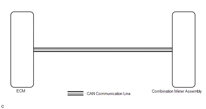
In this circuit, the combination meter assembly receives engine speed signals from the ECM via CAN communication. The combination meter assembly displays the engine speed calculated based on the data received from the ECM.
WIRING DIAGRAM
CAUTION / NOTICE / HINT
NOTICE:
- Before replacing the ECM, refer to Registration
- w/ Smart Key System:
Click here
.gif)
- w/o Smart Key System:
Click here
- w/ Smart Key System:
- When replacing the combination meter assembly, always replace it with a new one. If a combination meter assembly which was installed to another vehicle is used, the information stored in it will not match the information from the vehicle and a DTC may be stored.
PROCEDURE
|
1. |
CHECK FOR DTC (METER / GAUGE SYSTEM) |
(a) Check if meter / gauge system DTCs are output.
Click here
|
Result |
Proceed to |
|---|---|
|
Meter / gauge system DTCs are not output. |
A |
|
Meter / gauge system DTCs are output. |
B |
| B | .gif) |
GO TO DIAGNOSTIC TROUBLE CODE CHART |
|
.gif)
|
2. |
CHECK FOR DTC (SFI SYSTEM) |
(a) Check if SFI system DTCs are output.
- w/ Canister Pump Module:
Click here
- w/o Canister Pump Module:
Click here
|
Result |
Proceed to |
|---|---|
|
SFI system DTCs are not output. |
A |
|
SFI system DTCs are output. |
B |
| B | |
GO TO DIAGNOSTIC TROUBLE CODE CHART |
|
|
3. |
PERFORM ACTIVE TEST USING TECHSTREAM (ENGINE SPEED, ENGINE RPM) |
(a) Connect the Techstream to the DLC3.
(b) Turn the ignition switch to ON.
(c) Turn the Techstream on.
(d) Enter the following menus:
(1) for Engine: Powertrain / Engine and ECT / Data List.
(2) for Combination Meter: Body Electrical / Combination Meter / Data List.
(e) Read the Data List according to the display on the Techstream.
(1) Engine and ECT
Powertrain > Engine and ECT > Data List|
Tester Display |
Measurement Item |
Range |
Normal Condition |
Diagnostic Note |
|---|---|---|---|---|
|
Engine Speed |
Engine speed |
Min.: 0 rpm, Max.: 16383 rpm |
710 to 810 rpm: Idling with warm engine |
When the crankshaft position sensor is malfunctioning, "Engine Speed" is approximately 0 rpm or varies greatly from the actual engine speed. |
|
Tester Display |
|---|
|
Engine Speed |
(2) Combination Meter.
Body Electrical > Combination Meter > Data List|
Tester Display |
Measurement Item |
Range |
Normal Condition |
Diagnostic Note |
|---|---|---|---|---|
|
Engine Rpm |
Engine speed |
Min.: 0 rpm, Max.:12750 rpm |
Almost the same as actual tachometer |
- |
|
Tester Display |
|---|
|
Engine Rpm |
|
Result |
Proceed to |
|---|---|
|
The Data List values of the ECUs do not match |
A |
|
The Data List values of the ECUs match |
B |
HINT:
- When the Data List values of the ECUs match, an internal malfunction of the ECM is suspected.
- When the Data List values of the ECUs do not match, a signal output malfunction of the ECM or an internal malfunction of the combination meter assembly is suspected.
| A | |
REPLACE ECM |
| B | |
REPLACE COMBINATION METER ASSEMBLY |
 Speedometer Malfunction
DESCRIPTION
The combination meter assembly receives vehicle speed signals from the skid control
ECU (brake actuator assembly) via CAN communication. The speed sensor detects the
wheel speed and s ...
 Engine Coolant Temperature Receiver Gauge Malfunction
DESCRIPTION
In this circuit, the combination meter assembly receives engine coolant temperature
signals from the ECM via CAN communication. The combination meter assembly displays
the engine cool ...
Other materials:
Toyota CH-R Service Manual > Navigation System: Satellite Radio Broadcast cannot be Received
CAUTION / NOTICE / HINT
NOTICE:
Some satellite radio broadcasts require payment. A contract must be made between
a satellite radio company and the user. If the contract expires, it will not be
possible to listen to the broadcast.
WIRING DIAGRAM
PROCEDURE
1.
CHECK ...
Toyota CH-R Service Manual > Roof Headlining: Reassembly
REASSEMBLY
PROCEDURE
1. INSTALL HEADLINING LIGHT CASE
(a) Align the markings on the roof headlining with the headlining light case
and install it using hot melt glue.
*a
Marking
-
-
2. INSTALL NO. 2 ANTENNA CORD SUB-ASSEMBLY
Click here ...
Toyota C-HR (AX20) 2023-2026 Owner's Manual
Toyota CH-R Owners Manual
- For safety and security
- Instrument cluster
- Operation of each component
- Driving
- Interior features
- Maintenance and care
- When trouble arises
- Vehicle specifications
- For owners
Toyota CH-R Service Manual
- Introduction
- Maintenance
- Audio / Video
- Cellular Communication
- Navigation / Multi Info Display
- Park Assist / Monitoring
- Brake (front)
- Brake (rear)
- Brake Control / Dynamic Control Systems
- Brake System (other)
- Parking Brake
- Axle And Differential
- Drive Shaft / Propeller Shaft
- K114 Cvt
- 3zr-fae Battery / Charging
- Networking
- Power Distribution
- Power Assist Systems
- Steering Column
- Steering Gear / Linkage
- Alignment / Handling Diagnosis
- Front Suspension
- Rear Suspension
- Tire / Wheel
- Tire Pressure Monitoring
- Door / Hatch
- Exterior Panels / Trim
- Horn
- Lighting (ext)
- Mirror (ext)
- Window / Glass
- Wiper / Washer
- Door Lock
- Heating / Air Conditioning
- Interior Panels / Trim
- Lighting (int)
- Meter / Gauge / Display
- Mirror (int)
- Power Outlets (int)
- Pre-collision
- Seat
- Seat Belt
- Supplemental Restraint Systems
- Theft Deterrent / Keyless Entry

0.0082