Toyota CH-R Service Manual: Back-up Light Bulb
Components
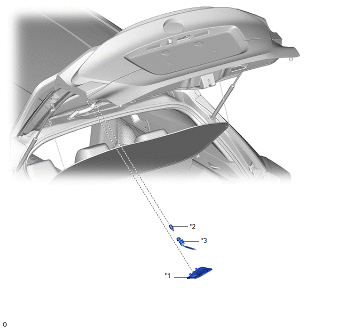
COMPONENTS
ILLUSTRATION
|
*1 |
BACK DOOR SERVICE HOLE COVER LH |
*2 |
BACK UP LIGHT BULB |
|
*3 |
BACK UP LIGHT SOCKET AND WIRE |
- |
- |
Removal
REMOVAL
CAUTION / NOTICE / HINT
HINT:
- Use the same procedure for the RH and LH sides.
- The procedure listed below is for the LH side.
PROCEDURE
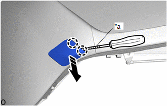
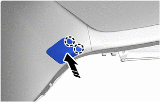
1. REMOVE BACK DOOR SERVICE HOLE COVER LH
(a) Using a screw driver with its tip wrapped in protective tape, disengage the claws to remove the back door service hole cover LH as shown in the illustration.
|
*a |
Protective Tape |
.png) |
Remove in this Direction |
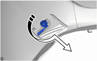
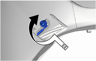
2. REMOVE BACK UP LIGHT BULB
(a) Turn the back up light socket and wire with the back up light bulb as shown in the illustration to disconnect them as a unit.
|
|
Remove in this Direction |
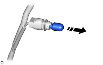
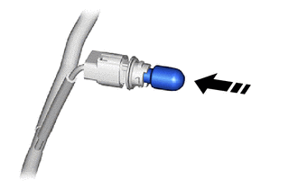
(b) Remove the back up light bulb from the back up light socket and wire as shown in the illustration.
|
|
Remove in this Direction |
Installation
INSTALLATION
CAUTION / NOTICE / HINT
HINT:
- Use the same procedure for the RH and LH sides.
- The procedure listed below is for the LH side.
PROCEDURE
1. INSTALL BACK UP LIGHT BULB
(a) Install the back up light bulb to the back up light socket and wire as shown in the illustration.
.png) |
Install in this Direction |
(b) Turn the back up light socket and wire with the back up light bulb as shown in the illustration to connect them as a unit.
|
|
Install in this Direction |
2. INSTALL BACK DOOR SERVICE HOLE COVER
(a) Engage the claws to install the back door service hole cover.
|
|
Install in this Direction |
 Air Conditioning Filter(for Valeo Made)
Components
COMPONENTS
ILLUSTRATION
*1
AIR FILTER COVER PLATE
*2
CLEAN AIR FILTER
*3
GLOVE COMPARTMENT DOOR ASSEMBLY
...
 Brake Fluid
Components
COMPONENTS
ILLUSTRATION
*A
for TMC Made
-
-
*1
CENTER NO. 1 COWL TOP VENTILATOR LOUVER
*2
...
Other materials:
Toyota CH-R Service Manual > Continuously Variable Transaxle System: Shift Solenoid "G" Control Circuit Low (Shift Solenoid Valve SC) (P099B,P099C)
DESCRIPTION
Based on the signal received by the shift solenoid valve SC, the ECM uses the
shift solenoid valve SLU to control the forward and reverse clutch pressure.
If there is an open or short in the shift solenoid valve SC circuit, the ECM
stops sending current to the defective shift solen ...
Toyota CH-R Service Manual > Audio And Visual System(for Radio And Display Type): Precaution
PRECAUTION
IGNITION SWITCH EXPRESSIONS
(a) The type of ignition switch used on this model differs depending on the specifications
of the vehicle. The expressions listed in the table below are used in this section.
Expression
Ignition Switch
(Position)
Engine ...
Toyota C-HR (AX20) 2023-2026 Owner's Manual
Toyota CH-R Owners Manual
- For safety and security
- Instrument cluster
- Operation of each component
- Driving
- Interior features
- Maintenance and care
- When trouble arises
- Vehicle specifications
- For owners
Toyota CH-R Service Manual
- Introduction
- Maintenance
- Audio / Video
- Cellular Communication
- Navigation / Multi Info Display
- Park Assist / Monitoring
- Brake (front)
- Brake (rear)
- Brake Control / Dynamic Control Systems
- Brake System (other)
- Parking Brake
- Axle And Differential
- Drive Shaft / Propeller Shaft
- K114 Cvt
- 3zr-fae Battery / Charging
- Networking
- Power Distribution
- Power Assist Systems
- Steering Column
- Steering Gear / Linkage
- Alignment / Handling Diagnosis
- Front Suspension
- Rear Suspension
- Tire / Wheel
- Tire Pressure Monitoring
- Door / Hatch
- Exterior Panels / Trim
- Horn
- Lighting (ext)
- Mirror (ext)
- Window / Glass
- Wiper / Washer
- Door Lock
- Heating / Air Conditioning
- Interior Panels / Trim
- Lighting (int)
- Meter / Gauge / Display
- Mirror (int)
- Power Outlets (int)
- Pre-collision
- Seat
- Seat Belt
- Supplemental Restraint Systems
- Theft Deterrent / Keyless Entry

0.0086