Toyota CH-R Service Manual: Test Mode Procedure
TEST MODE PROCEDURE
TEST MODE (SIGNAL CHECK MODE) PROCEDURE
HINT:
- When entering test mode (signal check mode), the tire pressure warning
ECU and receiver sets all the test mode (signal check mode) DTCs first.
After the tire pressure warning ECU and receiver completes the signal check for each inspection item, the DTCs for systems that are determined to be normal will be cleared.
The DTCs for other inspection items may not be cleared when only a certain signal is inspected.
- When test mode (signal check mode) returns to normal mode, all the test mode (signal check mode) DTCs will be cleared.
- During test mode (signal check mode), the system is not initialized even if the initialization procedure is performed.
(a) Turn the ignition switch off.
(b) Connect the Techstream to the DLC3.
(c) Turn the ignition switch to ON and the Techstream on.
(d) Enter the following menus: Chassis / Tire Pressure Monitor / Utility / Signal Check.
Chassis > Tire Pressure Monitor > Utility|
Tester Display |
|---|
|
Signal Check |
HINT:
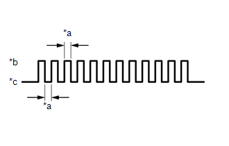
Every time the test mode (signal check mode) DTC clear conditions are satisfied, the tire pressure warning light illuminates for 1 second. Following this, the tire pressure warning light blinks at 0.125 second intervals.
|
*a |
0.125 sec. |
|
*b |
ON |
|
*c |
OFF |
(e) Tire pressure warning reset switch check (DTC C2198/98).
(1) Operate the steering pad switch assembly, select "TPMS" on the multi-information display and press the "ENTER" switch (steering pad switch assembly).
(f) Wait for 1.5 minutes with the vehicle stopped, or drive the vehicle at a speed of 50 km/h (31 mph) or more for 1 minute (DTCs C2181/81 to C2184/84 (C2185/85: w/ Full Size Spare Tire)).
HINT:
The tire pressure warning valve and transmitters send signals to the tire pressure warning ECU and receiver once every 1.5 minutes while the vehicle is stopped and once every minute while driving.
(g) Check that the tire pressure warning system test mode (signal check mode) DTCs are cleared.
|
Test Mode (Signal Check Mode) DTC |
Test Signal |
Test Mode (Signal Check Mode) DTC Clear Condition |
|---|---|---|
| *: w/ Full Size Spare Tire | ||
|
C2181/81 to C2184/84 (C2185/85*) |
Transmitter Data |
Data is received from the relevant transmitter which has a registered ID in the tire pressure warning ECU and receiver. |
|
C2198/98 |
Tire Pressure Warning Reset Switch Signal |
A signal is received indicating that the steering pad switch assembly is operated, "TPMS" on the multi-information display is selected and the "ENTER" switch (steering pad switch assembly) is pressed. |
(h) Result
HINT:
After the signal check is completed, check for test mode (signal check mode) DTCs to confirm the system status.
|
Condition |
Procedure |
|---|---|
|
Test mode (signal check mode) DTCs are output |
Repair the faulty part and enter Signal Check again |
|
Test mode (signal check mode) DTCs are cleared |
No problem |
(i) End of test mode (signal check mode)
(1) After completing test mode (signal check mode), turn the ignition switch off and disconnect the Techstream.
(j) Test mode (signal check mode) DTCs
(1) If a trouble code is displayed during the test mode (signal check mode) DTC check, check the diagnosis procedure listed for that code. For details of each code, refer to Link below.
|
DTC No. |
Detection Item |
Trouble Area |
Link |
|---|---|---|---|
| *: w/ Full Size Spare Tire | |||
|
C2181/81 |
Transmitter ID1 not received |
|
|
|
C2182/82 |
Transmitter ID2 not received |
|
|
|
C2183/83 |
Transmitter ID3 not received |
|
|
|
C2184/84 |
Transmitter ID4 not received |
|
|
|
C2185/85* |
Transmitter ID5 not received |
|
|
|
C2198/98 |
Initialization switch error |
|
|
.gif)
 Initialization
INITIALIZATION
NOTICE:
Initialization can be confirmed through the tire pressure warning light.
If the ignition switch off during initialization, the tire pressure
warning ECU and ...
 Problem Symptoms Table
PROBLEM SYMPTOMS TABLE
HINT:
Use the table below to help determine the cause of problem symptoms.
If multiple suspected areas are listed, the potential causes of the symptoms
are lis ...
Other materials:
Toyota CH-R Service Manual > Rear Trailing Arm: Installation
INSTALLATION
CAUTION / NOTICE / HINT
HINT:
Use the same procedure for the RH side and LH side.
The following procedure is for the LH side.
PROCEDURE
1. INSTALL REAR SUSPENSION ARM BRACKET
(a) Temporarily install the rear suspension arm bracket to the rear trailing
arm assem ...
Toyota CH-R Service Manual > Power Window Control System: System Diagram
SYSTEM DIAGRAM
Power Window Control System
Communication Table
Transmitting ECU
Receiving ECU
Signal
Communication Method
Multiplex Network Master Switch Assembly
Power Window Regulator Motor Assembly (for Driver Door)
...
Toyota C-HR (AX20) 2023-2026 Owner's Manual
Toyota CH-R Owners Manual
- For safety and security
- Instrument cluster
- Operation of each component
- Driving
- Interior features
- Maintenance and care
- When trouble arises
- Vehicle specifications
- For owners
Toyota CH-R Service Manual
- Introduction
- Maintenance
- Audio / Video
- Cellular Communication
- Navigation / Multi Info Display
- Park Assist / Monitoring
- Brake (front)
- Brake (rear)
- Brake Control / Dynamic Control Systems
- Brake System (other)
- Parking Brake
- Axle And Differential
- Drive Shaft / Propeller Shaft
- K114 Cvt
- 3zr-fae Battery / Charging
- Networking
- Power Distribution
- Power Assist Systems
- Steering Column
- Steering Gear / Linkage
- Alignment / Handling Diagnosis
- Front Suspension
- Rear Suspension
- Tire / Wheel
- Tire Pressure Monitoring
- Door / Hatch
- Exterior Panels / Trim
- Horn
- Lighting (ext)
- Mirror (ext)
- Window / Glass
- Wiper / Washer
- Door Lock
- Heating / Air Conditioning
- Interior Panels / Trim
- Lighting (int)
- Meter / Gauge / Display
- Mirror (int)
- Power Outlets (int)
- Pre-collision
- Seat
- Seat Belt
- Supplemental Restraint Systems
- Theft Deterrent / Keyless Entry

0.0102