Toyota CH-R Service Manual: Initialization
INITIALIZATION
NOTICE:
- Initialization can be confirmed through the tire pressure warning light.
- If the ignition switch off during initialization, the tire pressure warning ECU and receiver memorizes that initialization was being performed. Therefore, it is not necessary to perform the initialization procedure again after turning the ignition switch to ON.
- The order in which the data is received is random.
- If the signals from all the tire pressure warning valve and transmitters are received, initialization is completed.
- Initialization is completed when the Data List "ID Tire Inflation Pressure"
display shows the correct pressures.
Click here
.gif)
- Initialization is normally completed within a few minutes. However, it may take 10 minutes or more until the tire pressure of the tire inflation pressure display function is shown.
- It may take a few minutes until the values are displayed. If the values
are not displayed after a few minutes, perform troubleshooting according
to the inspection procedure for DTCs C2121/21 to C2124/24 (C2125/25: w/
Full Size Spare Tire).
Click here
- If initialization has not been completed successfully, DTC C2177/77 is stored after a vehicle speed of 40 km/h (25 mph) or more is detected for 20 minutes or more.
- During test mode (sensor check mode), the system will not change to initialization mode even if the tire pressure warning reset switch is pushed.
- Initialization can be terminated by connecting terminals 13 (TC) and
4 (CG) of the DLC3.
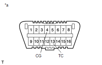
*a
Front view of DLC3
BEFORE INITIALIZATION
(a) Set the tire pressure to the specified value.
HINT:
Refer to the link, as the procedure for adjusting the tire pressures differs depending on the temperature of the tires.
Click here
HINT:
The tire pressure warning system illuminates the tire pressure warning light to warn the driver when the following condition is met:
- Due to the operation of the steering pad switch assembly, the tire pressure drops to approximately 75% or less of the tire pressure set during system initialization.
INITIALIZATION PROCEDURE
(a) Turn the ignition switch to ON.
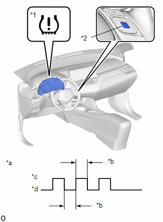
(b) Operate the steering pad switch assembly, select "TPMS" on the multi-information display and press and hold the "ENTER" switch (steering pad switch assembly) until the tire pressure warning light blinks 3 times.
|
*1 |
Tire Pressure Warning Light |
|
*2 |
"ENTER" Switch (Steering Pad Switch Assembly) |
|
*a |
Tire Pressure Warning Light Output Pattern |
|
*b |
1 sec. |
|
*c |
ON |
|
*d |
OFF |
(c) Turn the ignition switch off.
(d) Connect the Techstream to the DLC3.
(e) Turn the ignition switch to ON and turn the Techstream on.
(f) Enter the following menus: Chassis / Tire Pressure Monitor / Data List.
Chassis > Tire Pressure Monitor > Data List|
Tester Display |
Measurement Item |
Range |
Normal Condition |
Diagnostic Note |
|---|---|---|---|---|
|
ID 1 Tire Inflation Pressure |
ID1 tire inflation pressure |
min.: Absolute pressure (abs) / 0 kPa (0 kgf/cm2, 0 psi), Relative pressure (Gauge) / 0 kPa (0 kgf/cm2, 0 psi) max.: Absolute pressure (abs) / 480 kPa (4.9 kgf/cm2, 70 psi), Relative pressure (Gauge) / 380 kPa (3.9 kgf/cm2, 55 psi) |
Actual tire inflation pressure |
If N/A is displayed, data has not been received.*1 |
|
ID 2 Tire Inflation Pressure |
ID2 tire inflation pressure |
min.: Absolute pressure (abs) / 0 kPa (0 kgf/cm2, 0 psi), Relative pressure (Gauge) / 0 kPa (0 kgf/cm2, 0 psi) max.: Absolute pressure (abs) / 480 kPa (4.9 kgf/cm2, 70 psi), Relative pressure (Gauge) / 380 kPa (3.9 kgf/cm2, 55 psi) |
Actual tire inflation pressure |
If N/A is displayed, data has not been received.*1 |
|
ID 3 Tire Inflation Pressure |
ID3 tire inflation pressure |
min.: Absolute pressure (abs) / 0 kPa (0 kgf/cm2, 0 psi), Relative pressure (Gauge) / 0 kPa (0 kgf/cm2, 0 psi) max.: Absolute pressure (abs) / 480 kPa (4.9 kgf/cm2, 70 psi), Relative pressure (Gauge) / 380 kPa (3.9 kgf/cm2, 55 psi) |
Actual tire inflation pressure |
If N/A is displayed, data has not been received.*1 |
|
ID 4 Tire Inflation Pressure |
ID4 tire inflation pressure |
min.: Absolute pressure (abs) / 0 kPa (0 kgf/cm2, 0 psi), Relative pressure (Gauge) / 0 kPa (0 kgf/cm2, 0 psi) max.: Absolute pressure (abs) / 480 kPa (4.9 kgf/cm2, 70 psi), Relative pressure (Gauge) / 380 kPa (3.9 kgf/cm2, 55 psi) |
Actual tire inflation pressure |
If N/A is displayed, data has not been received.*1 |
|
ID 5 Tire Inflation Pressure |
ID5 tire inflation pressure |
min.: Absolute pressure (abs) / 0 kPa (0 kgf/cm2, 0 psi), Relative pressure (Gauge) / 0 kPa (0 kgf/cm2, 0 psi) max.: Absolute pressure (abs) / 480 kPa (4.9 kgf/cm2, 70 psi), Relative pressure (Gauge) / 380 kPa (3.9 kgf/cm2, 55 psi) |
Actual tire inflation pressure |
|
HINT:
- *1: It may take a few minutes until the values are displayed. If the
values are not displayed after a few minutes, perform troubleshooting according
to the inspection procedure for DTCs C2121/21 to C2124/24 (C2125/25: w/
Full Size Spare Tire).
Click here
- *2: w/ Full Size Spare Tire
(g) Check that initialization has been completed.
(h) Confirm that the tire pressure data of all tires is displayed on the Techstream screen.
 Registration
REGISTRATION
PROCEDURE
1. BEFORE REGISTRATION
NOTICE:
The transmitter ID is written on the tire pressure warning valve and transmitter.
It is not possible to read the transmitter ID after instal ...
 Test Mode Procedure
TEST MODE PROCEDURE
TEST MODE (SIGNAL CHECK MODE) PROCEDURE
HINT:
When entering test mode (signal check mode), the tire pressure warning
ECU and receiver sets all the test mode (signal ...
Other materials:
Toyota CH-R Service Manual > Door / Hatch: Back Door Support
Components
COMPONENTS
ILLUSTRATION
*1
BACK DOOR DAMPER STAY LOWER BRACKET
*2
BACK DOOR DAMPER STAY UPPER BRACKET
*3
BACK DOOR STAY ASSEMBLY
*4
STOP RING
N*m (kgf*cm, ft.*lbf ...
Toyota CH-R Service Manual > Pre-collision System: Front Camera Module Incorrect Axial Gap (C1AA8,C1AA9)
DESCRIPTION
If the millimeter wave radar sensor assembly detects that the forward recognition
camera beam has an axis misalignment, DTC C1AA8 is output.
Also if forward recognition axis adjustment has not been performed or did not
complete normally after the forward recognition camera was repl ...
Toyota C-HR (AX20) 2023-2026 Owner's Manual
Toyota CH-R Owners Manual
- For safety and security
- Instrument cluster
- Operation of each component
- Driving
- Interior features
- Maintenance and care
- When trouble arises
- Vehicle specifications
- For owners
Toyota CH-R Service Manual
- Introduction
- Maintenance
- Audio / Video
- Cellular Communication
- Navigation / Multi Info Display
- Park Assist / Monitoring
- Brake (front)
- Brake (rear)
- Brake Control / Dynamic Control Systems
- Brake System (other)
- Parking Brake
- Axle And Differential
- Drive Shaft / Propeller Shaft
- K114 Cvt
- 3zr-fae Battery / Charging
- Networking
- Power Distribution
- Power Assist Systems
- Steering Column
- Steering Gear / Linkage
- Alignment / Handling Diagnosis
- Front Suspension
- Rear Suspension
- Tire / Wheel
- Tire Pressure Monitoring
- Door / Hatch
- Exterior Panels / Trim
- Horn
- Lighting (ext)
- Mirror (ext)
- Window / Glass
- Wiper / Washer
- Door Lock
- Heating / Air Conditioning
- Interior Panels / Trim
- Lighting (int)
- Meter / Gauge / Display
- Mirror (int)
- Power Outlets (int)
- Pre-collision
- Seat
- Seat Belt
- Supplemental Restraint Systems
- Theft Deterrent / Keyless Entry

0.0108