Toyota CH-R Service Manual: Door Courtesy Switch Circuit
DESCRIPTION
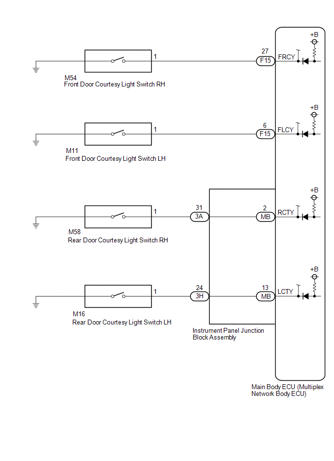
The main body ECU (multiplex network body ECU) detects the condition of the door courtesy light switch assembly.
WIRING DIAGRAM
CAUTION / NOTICE / HINT
NOTICE:
Before replacing the main body ECU (multiplex network body ECU), refer to Registration*1.
Click here .gif)
- *1: w/ Smart Key System
PROCEDURE
|
1. |
READ VALUE USING TECHSTREAM |
(a) Connect the Techstream to the DLC3.
(b) Turn the ignition switch to ON.
(c) Turn the Techstream on.
(d) Enter the following menus: Body Electrical / Main Body / Data List.
(e) Read the Data List according to the display on the Techstream.
Body Electrical > Main Body > Data List|
Tester Display |
Measurement Item |
Range |
Normal Condition |
Diagnostic Note |
|---|---|---|---|---|
|
RR Door Courtesy SW |
Rear door courtesy light switch assembly RH signal |
ON or OFF |
ON: Rear door RH open OFF: Rear door RH closed |
- |
|
RL Door Courtesy SW |
Rear door courtesy light switch assembly LH signal |
ON or OFF |
ON: Rear door LH open OFF: Rear door LH closed |
- |
|
FR Door Courtesy SW |
Front door courtesy light switch assembly RH signal |
ON or OFF |
ON: Front door RH open OFF: Front door RH closed |
- |
|
FL Door Courtesy SW |
Front door courtesy light switch assembly LH signal |
ON or OFF |
ON: Front door LH open OFF: Front door LH closed |
- |
|
Tester Display |
|---|
|
RR Door Courtesy SW |
|
RL Door Courtesy SW |
|
FR Door Courtesy SW |
|
FL Door Courtesy SW |
OK:
Normal conditions listed above are displayed.
|
Result |
Proceed to |
|---|---|
|
OK |
A |
|
FR Door Courtesy SW is not normal |
B |
|
FL Door Courtesy SW is not normal |
C |
|
RR Door Courtesy SW is not normal |
D |
|
RL Door Courtesy SW is not normal |
E |
| A | .gif) |
PROCEED TO NEXT SUSPECTED AREA SHOWN IN PROBLEM SYMPTOMS TABLE
|
| C | |
GO TO STEP 4 |
| D | |
GO TO STEP 6 |
| E | |
GO TO STEP 9 |
|
.gif)
|
2. |
INSPECT FRONT DOOR COURTESY LIGHT SWITCH ASSEMBLY RH |
(a) Remove the front door courtesy light switch assembly RH.
Click here
(b) Inspect the front door courtesy light switch assembly RH.
Click here
OK:
Front door courtesy light switch assembly RH is normal.
| NG | |
REPLACE FRONT DOOR COURTESY LIGHT SWITCH ASSEMBLY RH
|
|
|
3. |
CHECK HARNESS AND CONNECTOR (FRONT DOOR COURTESY LIGHT SWITCH ASSEMBLY RH - MAIN BODY ECU (MULTIPLEX NETWORK BODY ECU)) |
(a) Disconnect the F15 main body ECU (multiplex network body ECU) connector.
(b) Measure the resistance according to the value(s) in the table below.
Standard Resistance:
|
Tester Connection |
Condition |
Specified Condition |
|---|---|---|
|
M54-1 - F15-27 (FRCY) |
Always |
Below 1 Ω |
|
M54-1 or F15-27 (FRCY) - Body ground |
Always |
10 kΩ or higher |
| OK | |
REPLACE MAIN BODY ECU (MULTIPLEX NETWORK BODY ECU)
|
| NG | |
REPAIR OR REPLACE HARNESS OR CONNECTOR |
|
4. |
INSPECT FRONT DOOR COURTESY LIGHT SWITCH ASSEMBLY LH |
(a) Remove the front door courtesy light switch assembly LH.
Click here
(b) Inspect the front door courtesy light switch assembly LH.
Click here
OK:
Front door courtesy light switch assembly LH is normal.
| NG | |
REPLACE FRONT DOOR COURTESY LIGHT SWITCH ASSEMBLY LH
|
|
|
5. |
CHECK HARNESS AND CONNECTOR (FRONT DOOR COURTESY LIGHT SWITCH ASSEMBLY LH - MAIN BODY ECU (MULTIPLEX NETWORK BODY ECU)) |
(a) Disconnect the F15 main body ECU (multiplex network body ECU) connector.
(b) Measure the resistance according to the value(s) in the table below.
Standard Resistance:
|
Tester Connection |
Condition |
Specified Condition |
|---|---|---|
|
M11-1 - F15-6 (FLCY) |
Always |
Below 1 Ω |
|
M11-1 or F15-6 (FLCY) - Body ground |
Always |
10 kΩ or higher |
| OK | |
REPLACE MAIN BODY ECU (MULTIPLEX NETWORK BODY ECU)
|
| NG | |
REPAIR OR REPLACE HARNESS OR CONNECTOR |
|
6. |
INSPECT REAR DOOR COURTESY LIGHT SWITCH ASSEMBLY RH |
(a) Remove the rear door courtesy light switch assembly RH.
Click here
(b) Inspect the rear door courtesy light switch assembly RH.
Click here
| NG | |
REPLACE REAR DOOR COURTESY LIGHT SWITCH ASSEMBLY RH
|
|
|
7. |
CHECK HARNESS AND CONNECTOR (REAR DOOR COURTESY LIGHT SWITCH ASSEMBLY RH - INSTRUMENT PANEL JUNCTION BLOCK ASSEMBLY) |
(a) Disconnect the 3A instrument panel junction block assembly connector.
(b) Measure the resistance according to the value(s) in the table below.
Standard Resistance:
|
Tester Connection |
Condition |
Specified Condition |
|---|---|---|
|
M58-1 - 3A-31 |
Always |
Below 1 Ω |
|
M58-1 or 3A-31 - Body ground |
Always |
10 kΩ or higher |
| NG | |
REPAIR OR REPLACE HARNESS OR CONNECTOR |
|
|
8. |
INSPECT INSTRUMENT PANEL JUNCTION BLOCK ASSEMBLY |
(a) Remove the instrument panel junction block assembly.
Click here
(b) Remove the main body ECU (multiplex network body ECU) from the instrument panel junction block assembly.
Click here
(c) Measure the resistance according to the value(s) in the table below.
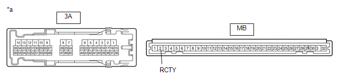
|
*a |
Component without harness connected (Instrument Panel Junction Block Assembly) |
- |
- |
Standard Resistance:
|
Tester Connection |
Condition |
Specified Condition |
|---|---|---|
|
3A-31 - MB-2 (RCTY) |
Always |
Below 1 Ω |
| OK | |
REPLACE MAIN BODY ECU (MULTIPLEX NETWORK BODY ECU)
|
| NG | |
REPLACE INSTRUMENT PANEL JUNCTION BLOCK ASSEMBLY
|
|
9. |
INSPECT REAR DOOR COURTESY LIGHT SWITCH ASSEMBLY LH |
(a) Remove the rear door courtesy light switch assembly LH.
Click here
(b) Inspect the rear door courtesy light switch assembly LH.
Click here
| NG | |
REPLACE REAR DOOR COURTESY LIGHT SWITCH ASSEMBLY LH
|
|
|
10. |
CHECK HARNESS AND CONNECTOR (REAR DOOR COURTESY LIGHT SWITCH ASSEMBLY LH - INSTRUMENT PANEL JUNCTION BLOCK ASSEMBLY) |
(a) Disconnect the 3H instrument panel junction block assembly connector.
(b) Measure the resistance according to the value(s) in the table below.
Standard Resistance:
|
Tester Connection |
Condition |
Specified Condition |
|---|---|---|
|
M16-1 - 3H-24 |
Always |
Below 1 Ω |
|
M16-1 or 3H-24 - Body ground |
Always |
10 kΩ or higher |
| NG | |
REPAIR OR REPLACE HARNESS OR CONNECTOR |
|
|
11. |
INSPECT INSTRUMENT PANEL JUNCTION BLOCK ASSEMBLY |
(a) Remove the instrument panel junction block assembly.
Click here
(b) Remove the main body ECU (multiplex network body ECU) from the instrument panel junction block assembly.
Click here
(c) Measure the resistance according to the value(s) in the table below.
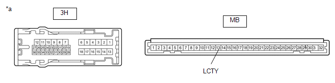
|
*a |
Component without harness connected (Instrument Panel Junction Block Assembly) |
- |
- |
Standard Resistance:
|
Tester Connection |
Condition |
Specified Condition |
|---|---|---|
|
3H-24 - MB-13 (LCTY) |
Always |
Below 1 Ω |
| OK | |
REPLACE MAIN BODY ECU (MULTIPLEX NETWORK BODY ECU)
|
| NG | |
REPLACE INSTRUMENT PANEL JUNCTION BLOCK ASSEMBLY
|
 Back Door Courtesy Switch Circuit
DESCRIPTION
The main body ECU (Multiplex Network Body ECU) receives a back door open/closed
signal from back door lock assembly.
WIRING DIAGRAM
CAUTION / NOTICE / HINT
NOTICE:
Before replacin ...
 Interior Light Circuit
DESCRIPTION
The main body ECU (multiplex network body ECU) controls the operation of the
following lights:
Map Light Assembly
No. 1 Room Light Assembly
WIRING DIAGRAM
CAUTION ...
Other materials:
Toyota CH-R Service Manual > Continuously Variable Transaxle System: Data List / Active Test
DATA LIST / ACTIVE TEST
DATA LIST
HINT:
Using the Techstream to read the Data List allows the values or states of switches,
sensors, actuators and other items to be read without removing any parts. This non-intrusive
inspection can be very useful because intermittent conditions or signals may ...
Toyota CH-R Service Manual > Lighting System: Engine Switch Illumination Circuit
DESCRIPTION
The illuminated entry system controls the engine switch illumination.
WIRING DIAGRAM
CAUTION / NOTICE / HINT
NOTICE:
Before replacing the certification ECU (smart key ECU assembly), refer to Registration.
Click here
PROCEDURE
1.
PERFORM ACTIVE TEST USIN ...
Toyota C-HR (AX20) 2023-2026 Owner's Manual
Toyota CH-R Owners Manual
- For safety and security
- Instrument cluster
- Operation of each component
- Driving
- Interior features
- Maintenance and care
- When trouble arises
- Vehicle specifications
- For owners
Toyota CH-R Service Manual
- Introduction
- Maintenance
- Audio / Video
- Cellular Communication
- Navigation / Multi Info Display
- Park Assist / Monitoring
- Brake (front)
- Brake (rear)
- Brake Control / Dynamic Control Systems
- Brake System (other)
- Parking Brake
- Axle And Differential
- Drive Shaft / Propeller Shaft
- K114 Cvt
- 3zr-fae Battery / Charging
- Networking
- Power Distribution
- Power Assist Systems
- Steering Column
- Steering Gear / Linkage
- Alignment / Handling Diagnosis
- Front Suspension
- Rear Suspension
- Tire / Wheel
- Tire Pressure Monitoring
- Door / Hatch
- Exterior Panels / Trim
- Horn
- Lighting (ext)
- Mirror (ext)
- Window / Glass
- Wiper / Washer
- Door Lock
- Heating / Air Conditioning
- Interior Panels / Trim
- Lighting (int)
- Meter / Gauge / Display
- Mirror (int)
- Power Outlets (int)
- Pre-collision
- Seat
- Seat Belt
- Supplemental Restraint Systems
- Theft Deterrent / Keyless Entry

0.0094