Toyota CH-R Service Manual: Interior Light Circuit
DESCRIPTION
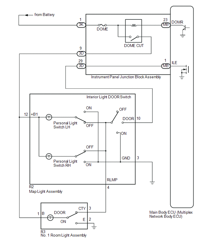
The main body ECU (multiplex network body ECU) controls the operation of the following lights:
- Map Light Assembly
- No. 1 Room Light Assembly
WIRING DIAGRAM
CAUTION / NOTICE / HINT
NOTICE:
- Inspect the fuses for circuits related to this system before performing the following procedure.
- Before replacing the main body ECU (multiplex network body ECU), refer
to Registration*1.
Click here
.gif)
- *1: w/ Smart Key System
HINT:
The DOME CUT relay supplies power to the interior lights. If all the lights that use power from the DOME CUT relay do not turn on, check the interior light auto cut circuit first.
Click here
PROCEDURE
|
1. |
PERFORM ACTIVE TEST USING TECHSTREAM |
(a) Connect the Techstream to the DLC3.
(b) Turn the ignition switch to ON.
(c) Turn the Techstream on.
(d) Enter the following menus: Body Electrical / Main Body / Active Test.
(e) Perform the Active Test according to the display on the Techstream.
Body Electrical > Main Body > Active Test|
Tester Display |
Measurement Item |
Control Range |
Diagnostic Note |
|---|---|---|---|
|
Illuminated Entry System |
Turns on the lights that are controlled by the illuminated entry system.* |
ON or OFF |
- |
- *: Refer to System Description for the lights that are controlled by
the illuminated entry system.
Click here
|
Tester Display |
|---|
|
Illuminated Entry System |
OK:
All lights that are controlled by the illuminated entry system come on.
| OK | .gif) |
PROCEED TO NEXT SUSPECTED AREA SHOWN IN PROBLEM SYMPTOMS TABLE
|
|
.gif)
|
2. |
INSPECT MAP LAMP ASSEMBLY |
(a) Remove the map light assembly.
Click here
(b) Inspect the map light assembly.
Click here
| NG | |
REPLACE MAP LAMP ASSEMBLY |
|
|
3. |
CHECK HARNESS AND CONNECTOR (MAP LIGHT ASSEMBLY - NO. 1 ROOM LIGHT ASSEMBLY) |
(a) Measure the resistance according to the value(s) in the table below.
Standard Resistance:
|
Tester Connection |
Condition |
Specified Condition |
|---|---|---|
|
R2-12(+B1) - R2-4 (RLMP) |
No. 1 room light switch in DOOR position |
Below 1 Ω |
|
No. 1 room light switch in ON position |
10 kΩ or higher |
|
|
R2-12 (+B1) or R2-4 (RLMP) - Body ground |
No. 1 room light switch in DOOR position |
10 kΩ or higher |
| NG | |
REPLACE NO. 1 ROOM LIGHT ASSEMBLY |
|
|
4. |
CHECK HARNESS AND CONNECTOR (DOME CUT RELAY - MAP LIGHT ASSEMBLY) |
(a) Measure the voltage according to the value(s) in the table below.
Standard Voltage:
|
Tester Connection |
Condition |
Specified Condition |
|---|---|---|
|
R2-12 (+B1) - Body ground |
Battery saving function not operating |
11 to 14 V |
| NG | |
REPAIR OR REPLACE HARNESS OR CONNECTOR |
|
|
5. |
CHECK HARNESS AND CONNECTOR (MAP LIGHT ASSEMBLY - INSTRUMENT PANEL JUNCTION BLOCK ASSEMBLY) |
(a) Disconnect the 3D instrument panel junction block assembly connector.
(b) Measure the resistance according to the value(s) in the table below.
Standard Resistance:
|
Tester Connection |
Condition |
Specified Condition |
|---|---|---|
|
R2-10 (DOOR) - 3D-29 |
Always |
Below 1 Ω |
|
R2-10 (DOOR) or 3D-29 - Body ground |
Always |
10 kΩ or higher |
| NG | |
REPAIR OR REPLACE HARNESS OR CONNECTOR |
|
|
6. |
INSPECT INSTRUMENT PANEL JUNCTION BLOCK ASSEMBLY |
(a) Remove the instrument panel junction block assembly.
Click here
(b) Remove the main body ECU (multiplex network body ECU) from the instrument panel junction block assembly.
Click here
(c) Measure the resistance according to the value(s) in the table below.
|
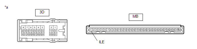
*a |
Component without harness connected (Instrument Panel Junction Block Assembly) |
- |
- |
Standard Resistance:
|
Tester Connection |
Condition |
Specified Condition |
|---|---|---|
|
3D-29 - MB-1 (ILE) |
Always |
Below 1 Ω |
| OK | |
REPLACE MAIN BODY ECU (MULTIPLEX NETWORK BODY ECU)
|
| NG | |
REPLACE INSTRUMENT PANEL JUNCTION BLOCK ASSEMBLY
|
 Door Courtesy Switch Circuit
DESCRIPTION
The main body ECU (multiplex network body ECU) detects the condition of the door
courtesy light switch assembly.
WIRING DIAGRAM
CAUTION / NOTICE / HINT
NOTICE:
Before replacing th ...
 Interior Light Auto Cut Circuit
DESCRIPTION
The main body ECU (multiplex network body ECU) controls operation of the DOME
CUT relay in order to supply power to the interior lights. When the battery saving
function operates whil ...
Other materials:
Toyota CH-R Service Manual > Lighting System: Problem Symptoms Table
PROBLEM SYMPTOMS TABLE
NOTICE:
Before replacing the main body ECU (multiplex network body ECU) or certification
ECU (smart key ECU assembly), refer to Registration*1.
Click here
*1: w/ Smart Key System
HINT:
Use the table below to help determine the cause of problem symptoms. ...
Toyota CH-R Service Manual > 3zr-fae Coolant: Replacement
REPLACEMENT
PROCEDURE
1. REMOVE NO. 1 ENGINE UNDER COVER
Click here
2. DRAIN ENGINE COOLANT
CAUTION:
When engine coolant is hot, do not remove the reserve tank cap, air
release valve or the radiator drain cock plug.
Fluid and steam may spray out due to high pressure, poss ...
Toyota C-HR (AX20) 2023-2026 Owner's Manual
Toyota CH-R Owners Manual
- For safety and security
- Instrument cluster
- Operation of each component
- Driving
- Interior features
- Maintenance and care
- When trouble arises
- Vehicle specifications
- For owners
Toyota CH-R Service Manual
- Introduction
- Maintenance
- Audio / Video
- Cellular Communication
- Navigation / Multi Info Display
- Park Assist / Monitoring
- Brake (front)
- Brake (rear)
- Brake Control / Dynamic Control Systems
- Brake System (other)
- Parking Brake
- Axle And Differential
- Drive Shaft / Propeller Shaft
- K114 Cvt
- 3zr-fae Battery / Charging
- Networking
- Power Distribution
- Power Assist Systems
- Steering Column
- Steering Gear / Linkage
- Alignment / Handling Diagnosis
- Front Suspension
- Rear Suspension
- Tire / Wheel
- Tire Pressure Monitoring
- Door / Hatch
- Exterior Panels / Trim
- Horn
- Lighting (ext)
- Mirror (ext)
- Window / Glass
- Wiper / Washer
- Door Lock
- Heating / Air Conditioning
- Interior Panels / Trim
- Lighting (int)
- Meter / Gauge / Display
- Mirror (int)
- Power Outlets (int)
- Pre-collision
- Seat
- Seat Belt
- Supplemental Restraint Systems
- Theft Deterrent / Keyless Entry

0.0087