Toyota CH-R Service Manual: Installation
INSTALLATION
PROCEDURE
1. INSTALL GLOVE BOX LIGHT ASSEMBLY
(a) Turn the glove box light assembly as shown in the illustration and install it.
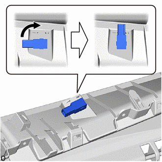
.png) |
Turn |
2. INSTALL NO. 2 INSTRUMENT PANEL LOWER FINISH PANEL
Click here .gif)
3. INSTALL GLOVE COMPARTMENT DOOR STOPPER SUB-ASSEMBLY
Click here
4. INSTALL GLOVE COMPARTMENT DOOR ASSEMBLY
Click here
5. INSTALL NO. 2 INSTRUMENT PANEL UNDER COVER SUB-ASSEMBLY
Click here
6. INSTALL COWL SIDE TRIM BOARD RH
HINT:
Use the same procedure as for the LH side.
Click here
7. INSTALL FRONT DOOR SCUFF PLATE RH
HINT:
Use the same procedure as for the LH side.
Click here
8. INSTALL REAR CONSOLE BOX ASSEMBLY
Click here
 Inspection
INSPECTION
PROCEDURE
1. INSPECT GLOVE BOX LIGHT ASSEMBLY
(a) Check that the LED illuminates.
(1) Apply battery voltage to the glove box light assembly and check that
the LED illum ...
 Lighting System
...
Other materials:
Toyota CH-R Service Manual > Navigation System: Cellular Phone Inspection
PROCEDURE
1.
CHECK USAGE CONDITION
(a) Check that the vehicle and cellular phone meet the following conditions:
NOTICE:
If changing cellular phone settings, updating software, etc. is necessary, make
sure to obtain the permission of the customer before performin ...
Toyota CH-R Service Manual > Automatic Headlight Beam Level Control System: Diagnostic Trouble Code Chart
DIAGNOSTIC TROUBLE CODE CHART
Automatic Headlight Beam Level Control System
DTC No.
Detection Item
Link
B2415
Vehicle Speed Sensor Malfunction
B2416
Height Control Sensor Malfunction
...
Toyota C-HR (AX20) 2023-2026 Owner's Manual
Toyota CH-R Owners Manual
- For safety and security
- Instrument cluster
- Operation of each component
- Driving
- Interior features
- Maintenance and care
- When trouble arises
- Vehicle specifications
- For owners
Toyota CH-R Service Manual
- Introduction
- Maintenance
- Audio / Video
- Cellular Communication
- Navigation / Multi Info Display
- Park Assist / Monitoring
- Brake (front)
- Brake (rear)
- Brake Control / Dynamic Control Systems
- Brake System (other)
- Parking Brake
- Axle And Differential
- Drive Shaft / Propeller Shaft
- K114 Cvt
- 3zr-fae Battery / Charging
- Networking
- Power Distribution
- Power Assist Systems
- Steering Column
- Steering Gear / Linkage
- Alignment / Handling Diagnosis
- Front Suspension
- Rear Suspension
- Tire / Wheel
- Tire Pressure Monitoring
- Door / Hatch
- Exterior Panels / Trim
- Horn
- Lighting (ext)
- Mirror (ext)
- Window / Glass
- Wiper / Washer
- Door Lock
- Heating / Air Conditioning
- Interior Panels / Trim
- Lighting (int)
- Meter / Gauge / Display
- Mirror (int)
- Power Outlets (int)
- Pre-collision
- Seat
- Seat Belt
- Supplemental Restraint Systems
- Theft Deterrent / Keyless Entry

0.0068