Toyota CH-R Service Manual: Installation
INSTALLATION
CAUTION / NOTICE / HINT
HINT:
- Use the same procedure for the RH side and LH side.
- The following procedure is for the LH side.
PROCEDURE
1. INSTALL NO. 1 SIDE AIRBAG SENSOR
(a) Check that the ignition switch off.
(b) Check that the cable is disconnected from the negative (-) battery terminal.
CAUTION:
Wait at least 90 seconds after disconnecting the cable from the negative (-) battery terminal to disable the SRS system.
.png)
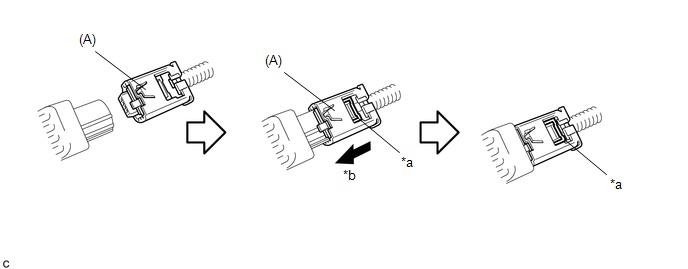
(c) Before connecting the connector, check that the position of the white housing lock is as shown in the illustration.
.png)
|
*a |
Correct |
*b |
Incorrect |
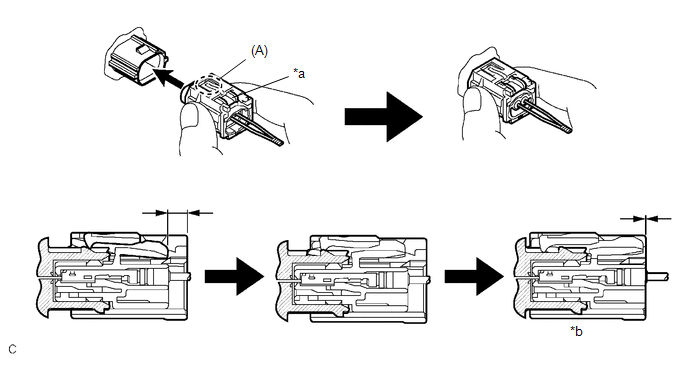
(d) Connect the connector to the No. 1 side airbag sensor.
|
*a |
White Housing Lock |
*b |
Connect |
NOTICE:
When connecting any airbag connector, take care not to damage the airbag wire harness.
HINT:
- Be sure to connect the connector until it is locked (when locking, make sure that a click sound can be heard).
- When the connector is locked, the white housing lock will slide. Do not hold the white housing lock or the part (A) as it may result in an insecure connection.
|
(e) Engage the claw to install the No. 1 side airbag sensor with the bolt. Torque: 9.0 N·m {92 kgf·cm, 80 in·lbf} NOTICE:
|
|
.png)
(f) Check that there is no looseness in the installed parts of the No. 1 side airbag sensor.
2. INSTALL FLOOR SIDE AIRBAG SENSOR
(a) Check that the ignition switch off.
(b) Check that the cable is disconnected from the negative (-) battery terminal.
CAUTION:
Wait at least 90 seconds after disconnecting the cable from the negative (-) battery terminal to disable the SRS system.
(c) Connect the connector to the floor side airbag sensor.
|
*a |
White Housing Lock |
*b |
Connection is completed |
NOTICE:
When connecting any airbag connector, take care not to damage the airbag wire harness.
HINT:
- Be sure to connect the connector until it is locked (when locking, make sure that a click sound can be heard).
- When the connector is locked, the white housing lock will slide. Do not hold the white housing lock or the part (A) as it may result in an insecure connection.
(d) Before connecting the connector, check that the position of the white housing lock is as shown in the illustration.
.png)
|
*a |
Incorrect |
*b |
Correct |
|
(e) Engage the claw to install the floor side airbag sensor with the bolt. Torque: 9.0 N·m {92 kgf·cm, 80 in·lbf} NOTICE:
|
|
.png)
(f) Check that there is no looseness in the installed parts of the floor side airbag sensor.
3. INSTALL CENTER PILLAR LOWER GARNISH
Click here .gif)
4. CONNECT REAR DOOR OPENING TRIM WEATHERSTRIP
5. INSTALL REAR DOOR SCUFF PLATE (w/ Rear Seat Side Airbag)
Click here
6. INSTALL REAR DOOR SCUFF PLATE (w/o Rear Seat Side Airbag)
Click here
7. CONNECT FRONT DOOR OPENING TRIM WEATHERSTRIP
8. INSTALL FRONT DOOR SCUFF PLATE
Click here
9. CONNECT FRONT SEAT OUTER BELT ASSEMBLY
Click here
10. INSTALL LAP BELT OUTER ANCHOR COVER
Click here
11. CONNECT CABLE TO NEGATIVE BATTERY TERMINAL
Click here
NOTICE:
When disconnecting the cable, some systems need to be initialized after the cable is reconnected.
Click here
12. PERFORM DIAGNOSTIC SYSTEM CHECK
Click here
13. INSPECT SRS WARNING LIGHT
Click here
 Removal
REMOVAL
CAUTION / NOTICE / HINT
The necessary procedures (adjustment, calibration, initialization, or registration)
that must be performed after parts are removed, installed, or replaced during th ...

Other materials:
Toyota CH-R Service Manual > Can Communication System: Check Bus 1 Line for Short to +B
DESCRIPTION
There may be a short circuit between one of the CAN bus lines and +B when no
resistance exists between terminal 23 (CA1H) of the central gateway ECU (network
gateway ECU) and terminal 16 (BAT) of the DLC3, or terminal 8 (CA1L) of the central
gateway ECU (network gateway ECU) and t ...
Toyota CH-R Owners Manual > Steps to take in an emergency: If the engine will not start
If the engine will not start even though correct starting procedures
are being followed, consider each of the following points:
The engine will not start even though the starter motor operates normally.
One of the following may be the cause of the problem:
There may not be sufficient fuel in ...
Toyota C-HR (AX20) 2023-2026 Owner's Manual
Toyota CH-R Owners Manual
- For safety and security
- Instrument cluster
- Operation of each component
- Driving
- Interior features
- Maintenance and care
- When trouble arises
- Vehicle specifications
- For owners
Toyota CH-R Service Manual
- Introduction
- Maintenance
- Audio / Video
- Cellular Communication
- Navigation / Multi Info Display
- Park Assist / Monitoring
- Brake (front)
- Brake (rear)
- Brake Control / Dynamic Control Systems
- Brake System (other)
- Parking Brake
- Axle And Differential
- Drive Shaft / Propeller Shaft
- K114 Cvt
- 3zr-fae Battery / Charging
- Networking
- Power Distribution
- Power Assist Systems
- Steering Column
- Steering Gear / Linkage
- Alignment / Handling Diagnosis
- Front Suspension
- Rear Suspension
- Tire / Wheel
- Tire Pressure Monitoring
- Door / Hatch
- Exterior Panels / Trim
- Horn
- Lighting (ext)
- Mirror (ext)
- Window / Glass
- Wiper / Washer
- Door Lock
- Heating / Air Conditioning
- Interior Panels / Trim
- Lighting (int)
- Meter / Gauge / Display
- Mirror (int)
- Power Outlets (int)
- Pre-collision
- Seat
- Seat Belt
- Supplemental Restraint Systems
- Theft Deterrent / Keyless Entry

0.0091