Toyota CH-R Service Manual: Removal
REMOVAL
CAUTION / NOTICE / HINT
The necessary procedures (adjustment, calibration, initialization, or registration) that must be performed after parts are removed, installed, or replaced during the side airbag sensor removal/installation are shown below.
Necessary Procedure After Parts Removed/Installed/Replaced|
Replacement Part or Procedure |
Necessary Procedures |
Effects / Inoperative when not performed |
Link |
|---|---|---|---|
|
Disconnect cable from negative battery terminal |
Initialize back door lock |
Power door lock control system |
|
|
Memorize steering angle neutral point |
Lane departure alert system (w/ Steering Control) |
|
|
|
Pre-collision system |
HINT:
- Use the same procedure for the RH side and LH side.
- The following procedure is for the LH side.
PROCEDURE
1. PRECAUTION
CAUTION:
Be sure to read Precaution thoroughly before servicing.
Click here .gif)
.png)
NOTICE:
After turning the ignition switch off, waiting time may be required before disconnecting the cable from the negative (-) battery terminal. Therefore, make sure to read the disconnecting the cable from the negative (-) battery terminal notices before proceeding with work.
Click here
2. DISCONNECT CABLE FROM NEGATIVE BATTERY TERMINAL
Click here
CAUTION:
- Wait at least 90 seconds after disconnecting the cable from the negative
(-) battery terminal to disable the SRS system.
.png)
- If an SRS part is accidentally deployed, it may cause a serious injury.
NOTICE:
When disconnecting the cable, some systems need to be initialized after the cable is reconnected.
Click here
3. REMOVE LAP BELT OUTER ANCHOR COVER
Click here
4. DISCONNECT FRONT SEAT OUTER BELT ASSEMBLY
Click here
5. REMOVE FRONT DOOR SCUFF PLATE
Click here
6. DISCONNECT FRONT DOOR OPENING TRIM WEATHERSTRIP
HINT:
Disconnect the front door opening trim weatherstrip to the extent that allows the removal of the center pillar lower garnish.
7. REMOVE REAR DOOR SCUFF PLATE (w/ Rear Seat Side Airbag)
Click here
8. REMOVE REAR DOOR SCUFF PLATE (w/o Rear Seat Side Airbag)
Click here
9. DISCONNECT REAR DOOR OPENING TRIM WEATHERSTRIP
HINT:
Disconnect the rear door opening trim weatherstrip to the extent that allows the removal of the center pillar lower garnish.
10. REMOVE CENTER PILLAR LOWER GARNISH
Click here
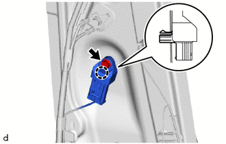
11. REMOVE NO. 1 SIDE AIRBAG SENSOR
(a) Check that the ignition switch off.
(b) Check that the cable is disconnected from the negative (-) battery terminal.
CAUTION:
Wait at least 90 seconds after disconnecting the cable from the negative (-) battery terminal to disable the SRS system.
|
(c) Remove the bolt and disengage the claw to separate the No. 1 side airbag sensor. |
|
(d) Disconnect the connector to remove the No. 1 side airbag sensor.
NOTICE:
When disconnecting any airbag connector, take care not to damage the airbag wire harness.
(1) Push down the white housing lock and slide the yellow CPA. (At this time, the connector cannot be disconnected yet.)
|
*a |
White Housing Lock |
*b |
Yellow CPA |
|
*c |
Slide |
*d |
Push |
(2) Push down the white housing lock again and disconnect the connector.
NOTICE:
Do not push down the part (A) shown in the illustration when disconnecting the connector.
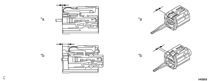
(e) After disconnecting the connector, check that the position of the white housing lock is as shown in the illustration.
.png)
|
*a |
Correct |
*b |
Incorrect |
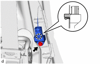
12. REMOVE FLOOR SIDE AIRBAG SENSOR
(a) Check that the ignition switch off.
(b) Check that the cable is disconnected from the negative (-) battery terminal.
CAUTION:
Wait at least 90 seconds after disconnecting the cable from the negative (-) battery terminal to disable the SRS system.
|
(c) Remove the bolt and disengage the claw to separate the floor side airbag sensor. |
|
(d) Disconnect the connector to remove the floor side airbag sensor.
NOTICE:
When disconnecting any airbag connector, take care not to damage the airbag wire harness.
(1) Push down the white housing lock and slide the yellow CPA. (At this time, the connector cannot be disconnected yet.)
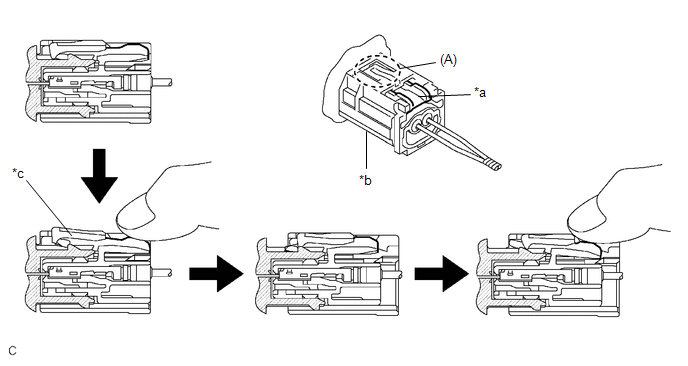
|
*a |
White Housing Lock |
*b |
Yellow CPA |
|
*c |
Connector lock is released |
- |
- |
(2) Push down the white housing lock again and disconnect the connector.
NOTICE:
Do not push down the part (A) shown in the illustration when disconnecting the connector.
(e) Check that the position of the white housing lock is as shown in the illustration.
|
*a |
Incorrect |
*b |
Correct |
 On-vehicle Inspection
ON-VEHICLE INSPECTION
CAUTION / NOTICE / HINT
CAUTION:
Be sure to correctly follow the removal and installation procedures for the side
airbag sensors.
PROCEDURE
1. INSPECT SIDE AIRBAG SENSOR ( ...
 Installation
INSTALLATION
CAUTION / NOTICE / HINT
HINT:
Use the same procedure for the RH side and LH side.
The following procedure is for the LH side.
PROCEDURE
1. INSTALL NO. 1 SIDE AIRBAG ...
Other materials:
Toyota CH-R Service Manual > Smart Key System(for Start Function): Steering Lock Position Signal Circuit Malfunction (B2285)
DESCRIPTION
This DTC is stored when the steering lock position signal sent by the steering
lock ECU (steering lock actuator or upper bracket assembly) via direct line and
the steering lock position signal sent via LIN communication do not match.
DTC No.
Detection Item
...
Toyota CH-R Service Manual > Back Door Courtesy Switch: Installation
INSTALLATION
PROCEDURE
1. INSTALL BACK DOOR LOCK ASSEMBLY
HINT:
Make sure to remove the string before installing a new back door lock assembly.
(a) Apply MP grease to the sliding parts of the back door lock assembly.
(b) Install the back door lock assembly with the 3 bolts.
Torque:
7.5 N·m ...
Toyota C-HR (AX20) 2023-2026 Owner's Manual
Toyota CH-R Owners Manual
- For safety and security
- Instrument cluster
- Operation of each component
- Driving
- Interior features
- Maintenance and care
- When trouble arises
- Vehicle specifications
- For owners
Toyota CH-R Service Manual
- Introduction
- Maintenance
- Audio / Video
- Cellular Communication
- Navigation / Multi Info Display
- Park Assist / Monitoring
- Brake (front)
- Brake (rear)
- Brake Control / Dynamic Control Systems
- Brake System (other)
- Parking Brake
- Axle And Differential
- Drive Shaft / Propeller Shaft
- K114 Cvt
- 3zr-fae Battery / Charging
- Networking
- Power Distribution
- Power Assist Systems
- Steering Column
- Steering Gear / Linkage
- Alignment / Handling Diagnosis
- Front Suspension
- Rear Suspension
- Tire / Wheel
- Tire Pressure Monitoring
- Door / Hatch
- Exterior Panels / Trim
- Horn
- Lighting (ext)
- Mirror (ext)
- Window / Glass
- Wiper / Washer
- Door Lock
- Heating / Air Conditioning
- Interior Panels / Trim
- Lighting (int)
- Meter / Gauge / Display
- Mirror (int)
- Power Outlets (int)
- Pre-collision
- Seat
- Seat Belt
- Supplemental Restraint Systems
- Theft Deterrent / Keyless Entry

0.0081