Toyota CH-R Service Manual: Tire And Wheel
Components
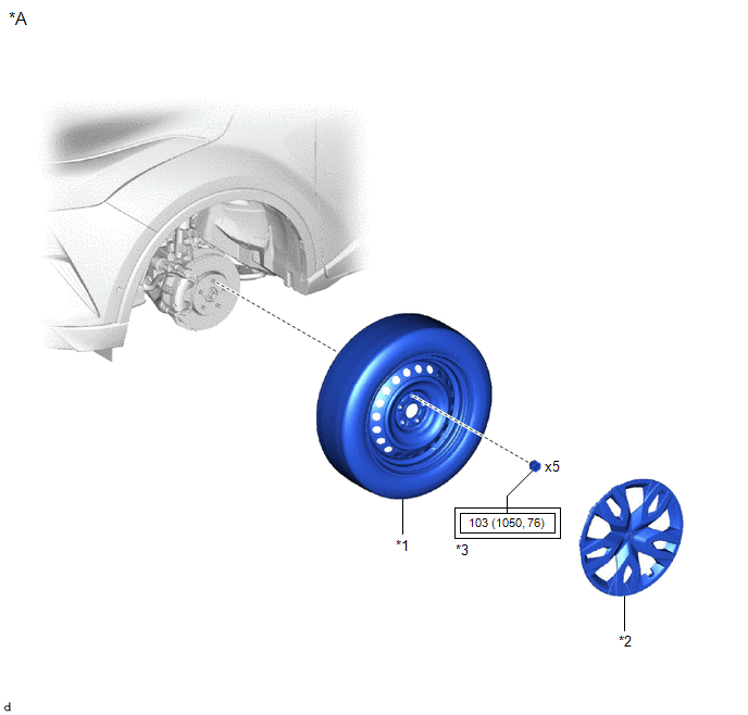
COMPONENTS
ILLUSTRATION
|
*A |
for Steel Wheel |
- |
- |
|
*1 |
WHEEL ASSEMBLY |
*2 |
WHEEL CAP |
|
*3 |
AXLE HUB NUT |
- |
- |
.png) |
Tightening torque for "Major areas involving basic vehicle performance such as moving/turning/stopping" : N*m (kgf*cm, ft.*lbf) |
- |
- |
ILLUSTRATION
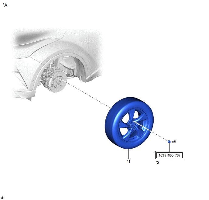
|
*A |
for Aluminum Wheel |
- |
- |
|
*1 |
WHEEL ASSEMBLY |
*2 |
AXLE HUB NUT |
|
|
Tightening torque for "Major areas involving basic vehicle performance such as moving/turning/stopping" : N*m (kgf*cm, ft.*lbf) |
- |
- |
Removal
REMOVAL
PROCEDURE
1. REMOVE WHEEL ASSEMBLY
(a) w/ Wheel Cap:
(1) Remove the wheel cap.
(b) Loosen the axle hub nuts approximately 90°.
(c) Lift up the vehicle and remove the axle hub nuts and wheel assembly.
Installation
INSTALLATION
PROCEDURE
1. INSTALL WHEEL ASSEMBLY
NOTICE:
- Only use axle hub nuts that are compatible with the wheel. If incompatible axle hub nuts are used, the contact surface of the wheel and axle hub nut may become deformed or damaged. This may result in looseness or loss of one or more axle hub nuts, even if they are tightened to the correct torque.
- Check that there is no foreign matter or rust on the axle hub bolts and the contact surfaces of the wheel, brake disc, axle hub, etc. Clean the contact surfaces and axle hub bolts if necessary. If a wheel assembly is installed with foreign matter or rust between the contact surfaces, the foreign matter or rust may work loose. This may result in looseness or loss of one or more axle hub nuts, even if they are tightened to the correct torque.
- When installing the axle hub nuts, clean the axle hub bolts with non-residue solvent and check that the axle hub nuts rotate smoothly by hand. If the axle hub nuts do not rotate smoothly, check that there is no foreign matter or rust and clean if necessary. If the axle hub nuts still do not rotate smoothly, replace the axle hub nuts and axle hub bolts with new ones.
(a) While aligning the wheel assembly with the center of the axle hub, install the axle hub nuts by hand.
|
(b) Temporarily tighten the axle hub nuts in the order shown in the illustration. |
|
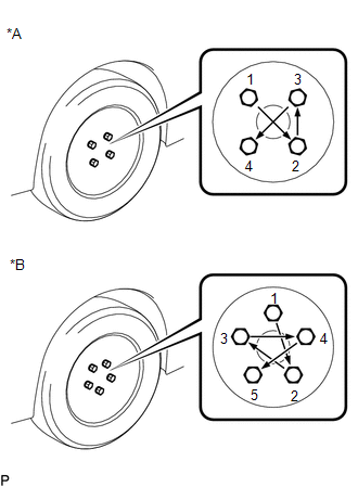
(c) Lower the vehicle then fully tighten the axle hub nuts in the order shown in the illustration.
Torque:
103 N·m {1050 kgf·cm, 76 ft·lbf}
(d) w/ Wheel Cap:
(1) Install the wheel cap.
 Installation
INSTALLATION
PROCEDURE
1. INSTALL REAR WIPER RUBBER
(a) Install the 2 rear wiper rubber backing plates to the rear wiper rubber.
Install in this Direction
NOTICE:
...
 Transmitter Battery(w/ Smart Key System)
Components
COMPONENTS
ILLUSTRATION
*1
TRANSMITTER BATTERY
*2
MECHANICAL KEY
*3
TRANSMITTER HOUSING COVER
*4
...
Other materials:
Toyota CH-R Service Manual > Charging System: Charging Failure
PROCEDURE
1.
CHECK GENERATOR PULLEY WITH CLUTCH (ON-VEHICLE INSPECTION)
(a) Start the engine and visually check that the generator rotor assembly (fan)
in the generator assembly is operating.
OK:
The generator rotor assembly (fan) is operating.
NG
...
Toyota CH-R Service Manual > Repair Instruction: Precaution
PRECAUTION
BASIC REPAIR HINT
(a) HINTS ON OPERATIONS
1
Attire
Always wear a clean uniform.
A hat and safety shoes must be worn.
2
Vehicle protection
Prepare a grille cover, fender cover, seat cove ...
Toyota C-HR (AX20) 2023-2026 Owner's Manual
Toyota CH-R Owners Manual
- For safety and security
- Instrument cluster
- Operation of each component
- Driving
- Interior features
- Maintenance and care
- When trouble arises
- Vehicle specifications
- For owners
Toyota CH-R Service Manual
- Introduction
- Maintenance
- Audio / Video
- Cellular Communication
- Navigation / Multi Info Display
- Park Assist / Monitoring
- Brake (front)
- Brake (rear)
- Brake Control / Dynamic Control Systems
- Brake System (other)
- Parking Brake
- Axle And Differential
- Drive Shaft / Propeller Shaft
- K114 Cvt
- 3zr-fae Battery / Charging
- Networking
- Power Distribution
- Power Assist Systems
- Steering Column
- Steering Gear / Linkage
- Alignment / Handling Diagnosis
- Front Suspension
- Rear Suspension
- Tire / Wheel
- Tire Pressure Monitoring
- Door / Hatch
- Exterior Panels / Trim
- Horn
- Lighting (ext)
- Mirror (ext)
- Window / Glass
- Wiper / Washer
- Door Lock
- Heating / Air Conditioning
- Interior Panels / Trim
- Lighting (int)
- Meter / Gauge / Display
- Mirror (int)
- Power Outlets (int)
- Pre-collision
- Seat
- Seat Belt
- Supplemental Restraint Systems
- Theft Deterrent / Keyless Entry

0.0082