Toyota CH-R Service Manual: Transmitter Battery(w/ Smart Key System)
Components
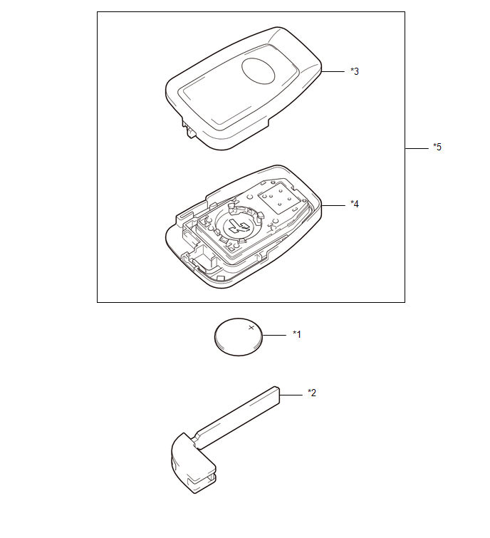
COMPONENTS
ILLUSTRATION
|
*1 |
TRANSMITTER BATTERY |
*2 |
MECHANICAL KEY |
|
*3 |
TRANSMITTER HOUSING COVER |
*4 |
TRANSMITTER HOUSING CASE |
|
*5 |
SMART KEY DOOR CONTROL TRANSMITTER HOUSING SET |
- |
- |
Removal
REMOVAL
CAUTION / NOTICE / HINT
NOTICE:
Take extra care when handling these precision electronic components.
PROCEDURE
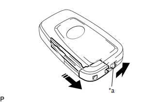
1. REMOVE TRANSMITTER BATTERY
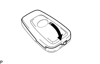
(a) Slide the release hook knob to remove the mechanical key as shown in the illustration.
|
*a |
Release Hook Knob |
.png) |
Remove in this Direction |
|
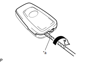
(b) Using a screwdriver with its tip wrapped in protective tape, pry apart the transmitter housing cover. NOTICE: Do not use excessive force when prying apart the transmitter housing cover. |
|
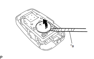
(c) Using a screwdriver with its tip wrapped in protective tape, remove the transmitter battery as shown in the illustration.
NOTICE:
- Do not push the terminals with your finger.
- Do not forcibly pry up the transmitter battery as the terminals may be damaged.
- Do not touch the transmitter battery with wet hands. Moisture may cause rust.
- Do not touch or move any components inside the transmitter housing case. It may interfere with proper operation.
- When replacing the transmitter battery, before starting work, remove static electricity that has built up in the body by touching, for example, the vehicle to prevent the electrical key transmitter sub-assembly from being damaged.
|
*a |
Protective Tape |
|
|
Remove in this Direction |
Installation
INSTALLATION
CAUTION / NOTICE / HINT
NOTICE:
Take extra care when handling these precision electronic components.
PROCEDURE
1. INSTALL TRANSMITTER BATTERY
(a) Install a new transmitter battery with the positive (+) side facing upward, as shown in the illustration.
NOTICE:
- Do not bend the transmitter battery electrode during installation.
- Keep the inside of the transmitter housing cover free of dust and oil.
- When replacing the transmitter battery, before starting work, remove static electricity that has built up in the body by touching, for example, the vehicle to prevent the electrical key transmitter sub-assembly from being damaged.
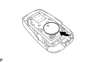
.png) |
Install in this Direction |
(b) Install the transmitter housing cover by pressing down on it as shown in the illustration.
|
|
Install in this Direction |
(c) Insert the mechanical key into the transmitter as shown in the illustration.
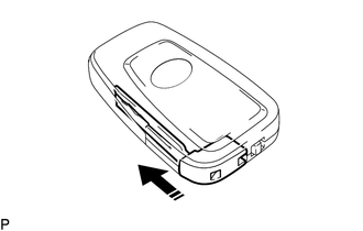
|
|
Install in this Direction |
(d) Press one of the transmitter switches and check that the LED illuminates.
OK:
Transmitter LED illuminates when a switch is pressed.
 Tire And Wheel
Components
COMPONENTS
ILLUSTRATION
*A
for Steel Wheel
-
-
*1
WHEEL ASSEMBLY
*2
WHEEL CAP
...
 Transmitter Battery(w/o Smart Key System)
Components
COMPONENTS
ILLUSTRATION
*1
DOOR CONTROL TRANSMITTER PACKING
*2
TRANSMITTER BATTERY
*3
TRANSMITTER HOUSING COVE ...
Other materials:
Toyota CH-R Service Manual > Rear Seat Side Airbag Assembly: Disposal
DISPOSAL
CAUTION / NOTICE / HINT
CAUTION:
Before performing pre-disposal deployment of any SRS part, review and closely
follow all applicable environmental and hazardous material regulations. Pre-disposal
deployment may be considered hazardous material treatment.
HINT:
Use the same ...
Toyota CH-R Service Manual > Navigation System: Lost Communication with Meter (B1324)
DESCRIPTION
This DTC is stored when a communication error occurs between the radio and display
receiver assembly and combination meter assembly.
DTC No.
Detection Item
DTC Detection Condition
Trouble Area
B1324
Lost Communic ...
Toyota C-HR (AX20) 2023-2026 Owner's Manual
Toyota CH-R Owners Manual
- For safety and security
- Instrument cluster
- Operation of each component
- Driving
- Interior features
- Maintenance and care
- When trouble arises
- Vehicle specifications
- For owners
Toyota CH-R Service Manual
- Introduction
- Maintenance
- Audio / Video
- Cellular Communication
- Navigation / Multi Info Display
- Park Assist / Monitoring
- Brake (front)
- Brake (rear)
- Brake Control / Dynamic Control Systems
- Brake System (other)
- Parking Brake
- Axle And Differential
- Drive Shaft / Propeller Shaft
- K114 Cvt
- 3zr-fae Battery / Charging
- Networking
- Power Distribution
- Power Assist Systems
- Steering Column
- Steering Gear / Linkage
- Alignment / Handling Diagnosis
- Front Suspension
- Rear Suspension
- Tire / Wheel
- Tire Pressure Monitoring
- Door / Hatch
- Exterior Panels / Trim
- Horn
- Lighting (ext)
- Mirror (ext)
- Window / Glass
- Wiper / Washer
- Door Lock
- Heating / Air Conditioning
- Interior Panels / Trim
- Lighting (int)
- Meter / Gauge / Display
- Mirror (int)
- Power Outlets (int)
- Pre-collision
- Seat
- Seat Belt
- Supplemental Restraint Systems
- Theft Deterrent / Keyless Entry

0.0104