Toyota CH-R Service Manual: Transmitter Battery(w/o Smart Key System)
Components
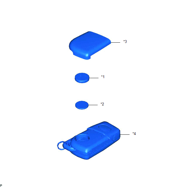
COMPONENTS
ILLUSTRATION
|
*1 |
DOOR CONTROL TRANSMITTER PACKING |
*2 |
TRANSMITTER BATTERY |
|
*3 |
TRANSMITTER HOUSING COVER |
*4 |
TRANSMITTER HOUSING CASE |
Removal
REMOVAL
CAUTION / NOTICE / HINT
NOTICE:
Take extra care when handling these precision electronic components.
PROCEDURE
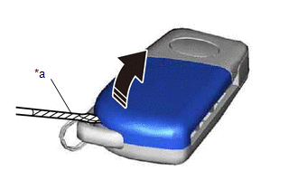
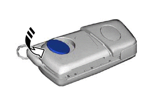
1. REMOVE TRANSMITTER HOUSING COVER
(a) Using a screwdriver with its tip wrapped in protective tape, remove the transmitter housing cover as shown in the illustration.
|
*a |
Protective Tape |
.png) |
Remove in this Direction |
NOTICE:
Do not use excessive force when prying apart the transmitter housing cover.
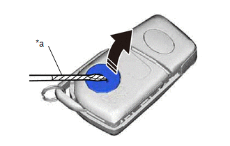
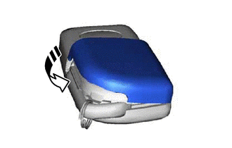
2. REMOVE DOOR CONTROL TRANSMITTER PACKING
(a) Using a screwdriver with its tip wrapped in protective tape, remove the door control transmitter packing as shown in the illustration.
|
*a |
Protective Tape |
|
|
Remove in this Direction |
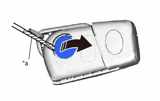
3. REMOVE TRANSMITTER BATTERY
(a) Using a screwdriver with its tip wrapped in protective tape, remove the transmitter battery as shown in the illustration.
|
*a |
Protective Tape |
|
|
Remove in this Direction |
NOTICE:
- Do not push the terminals with your finger.
- Do not forcibly pry up the transmitter battery as the terminals may be damaged.
- Do not touch the transmitter battery with wet hands. Moisture may cause rust.
- Do not touch or move any components inside the transmitter. It may interfere with proper operation.
- When replacing the transmitter battery, before starting work, remove static electricity that has built up in the body by touching, for example, the vehicle to prevent the electrical transmitter from being damaged.
Installation
INSTALLATION
CAUTION / NOTICE / HINT
NOTICE:
Take extra care when handling these precision electronic components.
PROCEDURE
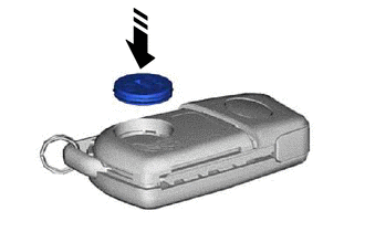
1. INSTALL TRANSMITTER BATTERY
(a) Install a new transmitter battery with the positive (+) side facing upward, as shown in the illustration.
.png) |
Install in this Direction |
NOTICE:
- Do not bend the transmitter battery electrode during installation.
- Keep the inside of the transmitter housing cover free of dust and oil.
- When replacing the transmitter battery, before starting work, remove static electricity that has built up in the body by touching, for example, the vehicle to prevent the electrical transmitter from being damaged.
2. INSTALL DOOR CONTROL TRANSMITTER PACKING
(a) Install the door control transmitter packing as shown in the illustration.
|
|
Install in this Direction |
3. INSTALL TRANSMITTER HOUSING COVER
(a) Install the transmitter housing cover as shown in the illustration.
|
|
Install in this Direction |
 Transmitter Battery(w/ Smart Key System)
Components
COMPONENTS
ILLUSTRATION
*1
TRANSMITTER BATTERY
*2
MECHANICAL KEY
*3
TRANSMITTER HOUSING COVER
*4
...
 Audio / Video
...
Other materials:
Toyota CH-R Service Manual > Power Door Lock Control System: Problem Symptoms Table
PROBLEM SYMPTOMS TABLE
HINT:
Use the table below to help determine the cause of problem symptoms.
If multiple suspected areas are listed, the potential causes of the symptoms
are listed in order of probability in the "Suspected Area" column of the
table. Check each sy ...
Toyota CH-R Service Manual > Power Mirror Control System: Customize Parameters
CUSTOMIZE PARAMETERS
CUSTOMIZE POWER MIRROR CONTROL SYSTEM
HINT:
The following items can be customized.
NOTICE:
When the customer requests a change in a function, first make sure that
the function can be customized.
Record the current settings before customizing.
(a) Cust ...
Toyota C-HR (AX20) 2023-2026 Owner's Manual
Toyota CH-R Owners Manual
- For safety and security
- Instrument cluster
- Operation of each component
- Driving
- Interior features
- Maintenance and care
- When trouble arises
- Vehicle specifications
- For owners
Toyota CH-R Service Manual
- Introduction
- Maintenance
- Audio / Video
- Cellular Communication
- Navigation / Multi Info Display
- Park Assist / Monitoring
- Brake (front)
- Brake (rear)
- Brake Control / Dynamic Control Systems
- Brake System (other)
- Parking Brake
- Axle And Differential
- Drive Shaft / Propeller Shaft
- K114 Cvt
- 3zr-fae Battery / Charging
- Networking
- Power Distribution
- Power Assist Systems
- Steering Column
- Steering Gear / Linkage
- Alignment / Handling Diagnosis
- Front Suspension
- Rear Suspension
- Tire / Wheel
- Tire Pressure Monitoring
- Door / Hatch
- Exterior Panels / Trim
- Horn
- Lighting (ext)
- Mirror (ext)
- Window / Glass
- Wiper / Washer
- Door Lock
- Heating / Air Conditioning
- Interior Panels / Trim
- Lighting (int)
- Meter / Gauge / Display
- Mirror (int)
- Power Outlets (int)
- Pre-collision
- Seat
- Seat Belt
- Supplemental Restraint Systems
- Theft Deterrent / Keyless Entry

0.007