Toyota CH-R Service Manual: Disassembly
DISASSEMBLY
PROCEDURE
1. REMOVE NO. 1 SIDE DEFROSTER NOZZLE
|
(a) Disengage the claws to remove the No. 1 side defroster nozzle. |
|
2. REMOVE NO. 2 SIDE DEFROSTER NOZZLE
|
(a) Disengage the claws to remove the No. 2 side defroster nozzle. |
|
3. REMOVE DEFROSTER NOZZLE ASSEMBLY
|
(a) Remove the 3 screws <D>. |
|
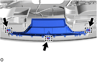
(b) Disengage the guides to remove the defroster nozzle assembly.
4. REMOVE TELEPHONE AND GPS ANTENNA ASSEMBLY (for Radio and Display Type)
Click here .gif)
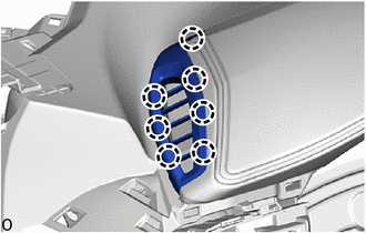
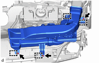
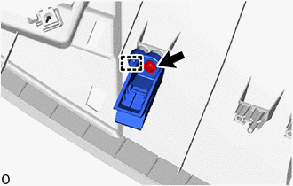
5. REMOVE NO. 1 HEATER TO REGISTER DUCT SUB-ASSEMBLY
|
(a) Disengage the clamp to disconnect the No. 2 instrument panel wire. |
|
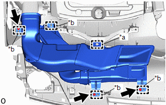
(b) Remove the 3 screws <D>.
(c) Disengage the guides to remove the No. 1 heater to register duct sub-assembly.
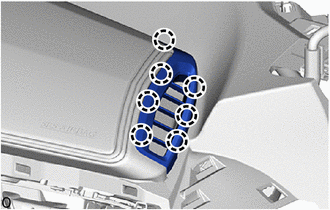
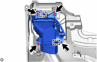
6. REMOVE NO. 3 HEATER TO REGISTER DUCT SUB-ASSEMBLY
|
(a) Remove the 3 screws <D>. |
|
(b) Disengage the guides to remove the No. 3 heater to register duct sub-assembly.
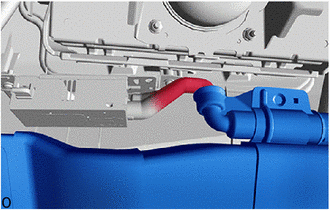
|
(c) w/ Ion Generator: (1) Disconnect the rear air duct sub-assembly. |
|
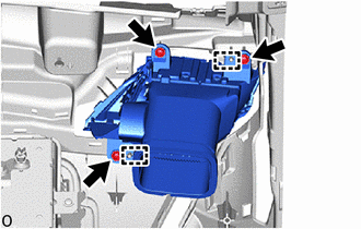
7. REMOVE NO. 1 INSTRUMENT PANEL REGISTER ASSEMBLY
|
(a) Remove the 4 screws <D>. |
|
(b) Disengage the guides to remove the No. 1 instrument panel register assembly.
8. REMOVE NO. 2 INSTRUMENT PANEL REGISTER ASSEMBLY
|
(a) Remove the 3 screws <D>. |
|
(b) Disengage the guides to remove the No. 2 instrument panel register assembly.
9. REMOVE INSTRUMENT PANEL PASSENGER AIRBAG ASSEMBLY
Click here
10. REMOVE ION GENERATOR SUB-ASSEMBLY (w/ Ion Generator)
Click here
11. REMOVE ANTENNA CORD SUB-ASSEMBLY
Click here
12. REMOVE AUTOMATIC LIGHT CONTROL SENSOR
Click here
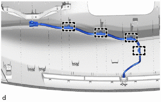
13. REMOVE NO. 2 INSTRUMENT PANEL WIRE
|
(a) w/ Ion Generator: (1) Disengage the clamps to remove the No. 2 instrument panel wire. |
|
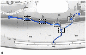
(b) w/o Ion Generator:
|
(1) Disengage the clamps to remove the No. 2 instrument panel wire. |
|
14. REMOVE NO. 1 INSTRUMENT PANEL PIN
HINT:
Use the same procedure as for the opposite side.
|
(a) Remove the screw <D>. |
|
(b) Disengage the guide to remove the No. 1 instrument panel pin.
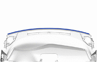
15. REMOVE NO. 1 INSTRUMENT PANEL CUSHION
|
(a) Remove the No. 1 instrument panel cushion. |
|
 Removal
REMOVAL
CAUTION / NOTICE / HINT
The necessary procedures (adjustment, calibration, initialization, or registration)
that must be performed after parts are removed, installed, or replaced during th ...
 Reassembly
REASSEMBLY
PROCEDURE
1. INSTALL NO. 1 INSTRUMENT PANEL CUSHION
(a) Install a new instrument panel cushion as shown in the illustration.
Standard Measurement:
Area ...
Other materials:
Toyota CH-R Service Manual > Smart Key System(for Entry Function): Front Passenger Side Door Entry Unlock Function does not Operate
DESCRIPTION
If the entry unlock function does not operate for the front passenger door only,
but the entry lock function operates, the request code is being transmitted properly
from the front passenger door. In this case, there may be a problem related to the
unlock sensor (connection betwee ...
Toyota CH-R Service Manual > 3zr-fae Coolant: Replacement
REPLACEMENT
PROCEDURE
1. REMOVE NO. 1 ENGINE UNDER COVER
Click here
2. DRAIN ENGINE COOLANT
CAUTION:
When engine coolant is hot, do not remove the reserve tank cap, air
release valve or the radiator drain cock plug.
Fluid and steam may spray out due to high pressure, poss ...
Toyota C-HR (AX20) 2023-2026 Owner's Manual
Toyota CH-R Owners Manual
- For safety and security
- Instrument cluster
- Operation of each component
- Driving
- Interior features
- Maintenance and care
- When trouble arises
- Vehicle specifications
- For owners
Toyota CH-R Service Manual
- Introduction
- Maintenance
- Audio / Video
- Cellular Communication
- Navigation / Multi Info Display
- Park Assist / Monitoring
- Brake (front)
- Brake (rear)
- Brake Control / Dynamic Control Systems
- Brake System (other)
- Parking Brake
- Axle And Differential
- Drive Shaft / Propeller Shaft
- K114 Cvt
- 3zr-fae Battery / Charging
- Networking
- Power Distribution
- Power Assist Systems
- Steering Column
- Steering Gear / Linkage
- Alignment / Handling Diagnosis
- Front Suspension
- Rear Suspension
- Tire / Wheel
- Tire Pressure Monitoring
- Door / Hatch
- Exterior Panels / Trim
- Horn
- Lighting (ext)
- Mirror (ext)
- Window / Glass
- Wiper / Washer
- Door Lock
- Heating / Air Conditioning
- Interior Panels / Trim
- Lighting (int)
- Meter / Gauge / Display
- Mirror (int)
- Power Outlets (int)
- Pre-collision
- Seat
- Seat Belt
- Supplemental Restraint Systems
- Theft Deterrent / Keyless Entry

0.0082