Toyota CH-R Service Manual: Removal
REMOVAL
PROCEDURE
1. REMOVE FRONT DOOR SCUFF PLATE LH
Click here
.gif)
2. REMOVE COWL SIDE TRIM BOARD LH
Click here
3. REMOVE NO. 2 INSTRUMENT PANEL UNDER COVER SUB-ASSEMBLY
Click here
4. REMOVE NO. 1 AIR DUCT
Click here
5. REMOVE NO. 2 HEATER COVER (for VALEO Made)
|
(a) Disengage the clamp. |
|
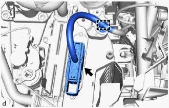
(b) Disconnect the connector.
|
(c) Remove the screw and No. 2 heater cover. |
|
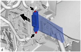
6. REMOVE NO. 2 HEATER COVER (for DENSO Made)
|
(a) Disengage the clamp. |
|
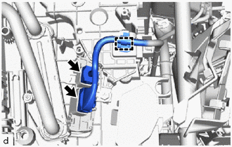
(b) Disconnect the 2 connectors.
|
(c) Remove the screw. |
|
(d) Disengage the claw and guide to remove the No. 2 heater cover.
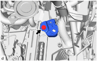
7. REMOVE QUICK HEATER ASSEMBLY (for VALEO Made)
(a) Remove the 2 screws and quick heater assembly as shown in the illustration.
.png) |
Remove in this Direction |
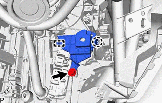
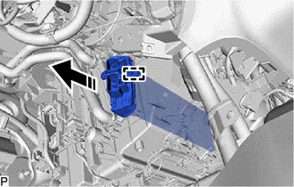
8. REMOVE QUICK HEATER ASSEMBLY (for DENSO Made)
(a) Disengage the guide to remove the quick heater assembly as shown in the illustration.
|
|
Remove in this Direction |
 Inspection
INSPECTION
PROCEDURE
1. INSPECT QUICK HEATER ASSEMBLY (for VALEO Made)
(a) Check the resistance.
(1) Measure the resistance according to the value(s) in the table below.
Standard R ...
 Installation
INSTALLATION
PROCEDURE
1. INSTALL QUICK HEATER ASSEMBLY (for VALEO Made)
(a) Install the quick heater assembly with the 2 screws as shown in the illustration.
Install in this ...
Other materials:
Toyota CH-R Service Manual > Continuously Variable Transaxle System: Precaution
PRECAUTION
IGNITION SWITCH EXPRESSION
HINT:
The type of ignition switch used on this model differs depending on the specifications
of the vehicle. The expressions listed in the table below are used in this section.
Expression
Ignition Switch (Position)
Engine S ...
Toyota CH-R Service Manual > Window Defogger System: Precaution
PRECAUTION
IGNITION SWITCH EXPRESSIONS
(a) The type of ignition switch used on this model differs according to the specifications
of the vehicle. The expressions listed in the table below are used in this section.
Expression
Ignition Switch (Position)
Engine Swi ...
Toyota C-HR (AX20) 2023-2026 Owner's Manual
Toyota CH-R Owners Manual
- For safety and security
- Instrument cluster
- Operation of each component
- Driving
- Interior features
- Maintenance and care
- When trouble arises
- Vehicle specifications
- For owners
Toyota CH-R Service Manual
- Introduction
- Maintenance
- Audio / Video
- Cellular Communication
- Navigation / Multi Info Display
- Park Assist / Monitoring
- Brake (front)
- Brake (rear)
- Brake Control / Dynamic Control Systems
- Brake System (other)
- Parking Brake
- Axle And Differential
- Drive Shaft / Propeller Shaft
- K114 Cvt
- 3zr-fae Battery / Charging
- Networking
- Power Distribution
- Power Assist Systems
- Steering Column
- Steering Gear / Linkage
- Alignment / Handling Diagnosis
- Front Suspension
- Rear Suspension
- Tire / Wheel
- Tire Pressure Monitoring
- Door / Hatch
- Exterior Panels / Trim
- Horn
- Lighting (ext)
- Mirror (ext)
- Window / Glass
- Wiper / Washer
- Door Lock
- Heating / Air Conditioning
- Interior Panels / Trim
- Lighting (int)
- Meter / Gauge / Display
- Mirror (int)
- Power Outlets (int)
- Pre-collision
- Seat
- Seat Belt
- Supplemental Restraint Systems
- Theft Deterrent / Keyless Entry

0.0072