Toyota CH-R Service Manual: Lost Communication with Blind Spot Monitor Slave Module (U0232)
DESCRIPTION
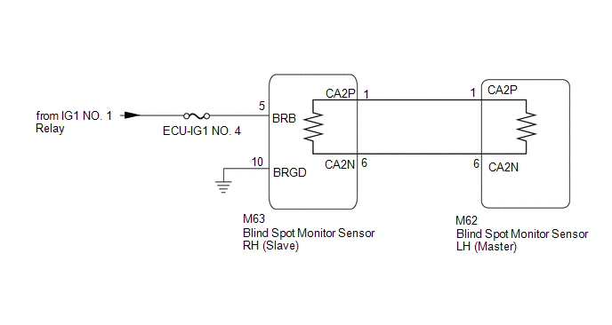
This DTC is stored when the blind spot monitor sensor LH (Master) judges that there is a communication problem with the blind spot monitor sensor RH (Slave).
|
DTC No. |
Detection Item |
DTC Detection Condition |
Trouble Area |
|---|---|---|---|
|
U0232 |
Lost Communication with Blind Spot Monitor Slave Module |
The blind spot monitor sensor LH (Master) cannot receive signals from the blind spot monitor sensor RH (Slave). |
|
WIRING DIAGRAM
CAUTION / NOTICE / HINT
NOTICE:
- When checking for DTCs, make sure that the blind spot monitor system is on.
- Inspect the fuses for circuits related to this system before performing the following inspection procedure.
- Before measuring the resistance of the CAN bus, turn the ignition switch off and leave the vehicle for 1 minute or more without operating the key or any switches, or opening or closing the doors. After that, disconnect the cable from the negative (-) battery terminal and leave the vehicle for 1 minute or more before measuring the resistance.
- After turning the ignition switch off, waiting time may be required
before disconnecting the cable from the negative (-) battery terminal. Therefore,
make sure to read the disconnecting the cable from the negative (-) battery
terminal notices before proceeding with work.
Click here
.gif)
HINT:
- Operating the ignition switch, any other switches or a door triggers related ECU and sensor communication on the CAN. This communication will cause the resistance value to change.
- Even after DTCs are cleared, if a DTC is stored again after driving the vehicle for a while, the malfunction may be occurring due to vibration of the vehicle. In such a case, wiggling the ECUs or wire harness while performing the inspection below may help determine the cause of the malfunction.
PROCEDURE
|
1. |
CHECK CAN BUS MAIN WIRE |
|
(a) Disconnect the cable from the negative (-) battery terminal. |
|
(b) Measure the resistance according to the value(s) in the table below.
Standard Resistance:
|
Tester Connection |
Condition |
Specified Condition |
Result |
|---|---|---|---|
|
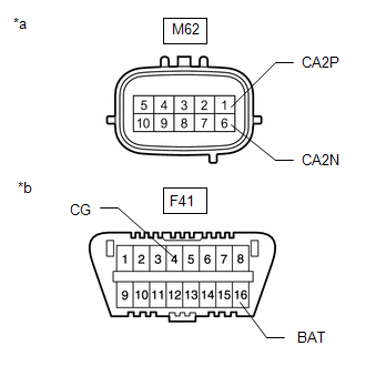
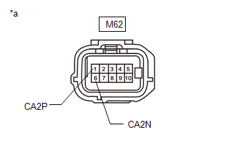
M62-1 (CA2P) -M62-6 (CA2N) |
Cable disconnected from negative (-) battery terminal |
54 to 69 Ω |
Below 54 Ω: Short circuit between bus lines |
|
70 Ω or more: Open circuit in main bus lines |
|||
|
M62-1(CA2P) - F41-4(CG) |
Cable disconnected from negative (-) battery terminal |
200 Ω or higher |
Below 200 Ω: CA2P short to ground |
|
M62-6(CA2N) - F41-4(CG) |
Cable disconnected from negative (-) battery terminal |
200 Ω or higher |
Below 200 Ω: CA2N short to ground |
|
M62-1(CA2P) - F41-16(BAT) |
Cable disconnected from negative (-) battery terminal |
6 kΩ or higher |
Below 6 kΩ: CA2P +B short |
|
M62-6(CA2N) - F41-16(BAT) |
Cable disconnected from negative (-) battery terminal |
6 kΩ or higher |
Below 6 kΩ: CA2N +B short |
|
Result |
Proceed to |
|---|---|
|
OK |
A |
|
Open circuit in CAN main bus lines |
B |
|
Short circuit between bus lines |
C |
|
D |
| B | .gif) |
GO TO STEP 6 |
| C | |
GO TO STEP 8 |
| D | |
GO TO STEP 10 |
|
.gif)
|
2. |
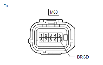
CHECK HARNESS AND CONNECTOR (BLIND SPOT MONITOR SENSOR RH (SLAVE) - BODY GROUND) |
|
(a) Disconnect the blind spot monitor sensor RH (Slave) connector. |
|
(b) Measure the resistance according to the value(s) in the table below.
Standard Resistance:
|
Tester Connection |
Condition |
Specified Condition |
|---|---|---|
|
M63-10 (BRGD) - Body ground |
Always |
Below 1 Ω |
| NG | |
REPAIR OR REPLACE HARNESS OR CONNECTOR |
|
|
3. |
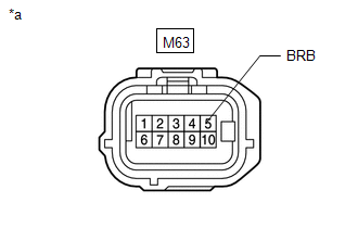
CHECK HARNESS AND CONNECTOR (BLIND SPOT MONITOR SENSOR RH (SLAVE) POWER SOURCE) |
|
(a) Disconnect the blind spot monitor sensor RH (Slave) connector. |
|
(b) Measure the voltage according to the value(s) in the table below.
Standard Voltage:
|
Tester Connection |
Switch Condition |
Specified Condition |
|---|---|---|
|
M63-5 (BRB) - Body ground |
Ignition switch to ON |
11 to 14 V |
|
M63-5 (BRB) - Body ground |
Ignition switch off |
Below 1 V |
| NG | |
REPAIR OR REPLACE HARNESS OR CONNECTOR |
|
|
4. |
CHECK DTC |
(a) Turn the ignition switch off.
(b) Turn the ignition switch on (IG).
(c) Check for DTCs.
Click here
OK:
No DTCs are output.
| OK | |
USE SIMULATION METHOD TO CHECK
|
|
|
5. |
REPLACE BLIND SPOT MONITOR SENSOR RH (SLAVE) |
(a) Replace the blind spot monitor sensor RH (Slave).
Click here
(b) Clear the DTCs.
Click here
(c) Recheck for DTCs and check if the same DTC is output again.
Click here
OK:
No DTCs are output.
| OK | |
END (BLIND SPOT MONITOR SENSOR RH (SLAVE) WAS DEFECTIVE) |
| NG | |
REPLACE BLIND SPOT MONITOR SENSOR LH (MASTER) |
|
6. |
CHECK FOR OPEN IN CAN BUS MAIN WIRE (BLIND SPOT MONITOR SENSOR RH (SLAVE)) |
(a) Disconnect the cable from the negative (-) battery terminal.
(b) Disconnect the blind spot monitor sensor RH (Slave) connector.
|
(c) Measure the resistance according to the value(s) in the table below. Standard Resistance:
|
|

| OK | |
REPLACE BLIND SPOT MONITOR SENSOR RH (SLAVE) |
|
|
7. |
CHECK FOR OPEN IN CAN BUS MAIN WIRE (BLIND SPOT MONITOR SENSOR LH (MASTER)) |
(a) Reconnect the blind spot monitor sensor RH (Slave) M63 connector.
(b) Disconnect the cable from the negative (-) battery terminal.
(c) Disconnect the blind spot monitor sensor LH (Master) connector.
|
(d) Measure the resistance according to the value(s) in the table below. Standard Resistance:
|
|
| OK | |
REPLACE BLIND SPOT MONITOR SENSOR LH (MASTER) |
| NG | |
REPAIR OR REPLACE CAN MAIN WIRE OR CONNECTOR (BLIND SPOT MONITOR SENSOR LH (MASTER) - BLIND SPOT MONITOR SENSOR RH (SLAVE)) |
|
8. |
CHECK FOR SHORT IN CAN BUS WIRES (BLIND SPOT MONITOR SENSOR RH (SLAVE)) |
|
(a) Disconnect the cable from the negative (-) battery terminal. |
|
(b) Disconnect the blind spot monitor sensor RH (Slave) connector.
(c) Measure the resistance according to the value(s) in the table below.
Standard Resistance:
|
Tester Connection |
Condition |
Specified Condition |
|---|---|---|
|
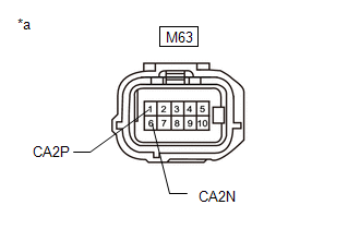
M63-1 (CA2P) - M63-6 (CA2N) |
Cable disconnected from negative (-) battery terminal |
108 to 132 Ω |
| OK | |
REPLACE BLIND SPOT MONITOR SENSOR RH (SLAVE) |
|
|
9. |
CHECK FOR SHORT IN CAN BUS WIRES (BLIND SPOT MONITOR SENSOR LH (MASTER)) |
(a) Reconnect the blind spot monitor sensor RH (Slave) M63 connector.
|
(b) Disconnect the cable from the negative (-) battery terminal. |
|
(c) Disconnect the blind spot monitor sensor LH (Master) connector.
(d) Measure the resistance according to the value(s) in the table below.
Standard Resistance:
|
Tester Connection |
Condition |
Specified Condition |
|---|---|---|
|
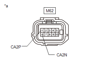
M62-1 (CA2P) - M62-6 (CA2N) |
Cable disconnected from negative (-) battery terminal |
108 to 132 Ω |
| OK | |
REPLACE BLIND SPOT MONITOR SENSOR LH (MASTER) |
| NG | |
REPAIR OR REPLACE CAN MAIN WIRE OR CONNECTOR (BLIND SPOT MONITOR SENSOR LH (MASTER) - BLIND SPOT MONITOR SENSOR RH (SLAVE)) |
|
10. |
CHECK FOR SHORT IN CAN BUS WIRES (BLIND SPOT MONITOR SENSOR RH (SLAVE)) |
|
(a) Disconnect the cable from the negative (-) battery terminal. |
|
(b) Disconnect the blind spot monitor sensor RH (Slave) connector.
(c) Measure the resistance according to the value(s) in the table below.
Standard Resistance:
|
Tester Connection |
Condition |
Specified Condition |
|---|---|---|
|
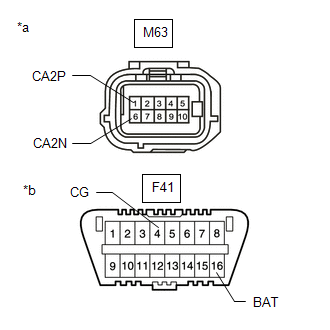
M63-1 (CA2P) - F41-4 (CG) |
Cable disconnected from negative (-) battery terminal |
200 Ω or higher |
|
M63-6 (CA2N) - F41-4 (CG) |
Cable disconnected from negative (-) battery terminal |
200 Ω or higher |
|
M63-1 (CA2P) - F41-16 (BAT) |
Cable disconnected from negative (-) battery terminal |
6 kΩ or higher |
|
M63-6 (CA2N) - F41-16 (BAT) |
Cable disconnected from negative (-) battery terminal |
6 kΩ or higher |
| OK | |
REPLACE BLIND SPOT MONITOR SENSOR RH (SLAVE) |
|
|
11. |
CHECK FOR SHORT IN CAN BUS WIRES (BLIND SPOT MONITOR SENSOR LH (MASTER)) |
(a) Reconnect the blind spot monitor sensor RH (Slave) M63 connector.
|
(b) Disconnect the cable from the negative (-) battery terminal. |
|

(c) Disconnect the blind spot monitor sensor LH (Master) connector.
(d) Measure the resistance according to the value(s) in the table below.
Standard Resistance:
|
Tester Connection |
Condition |
Specified Condition |
|---|---|---|
|
M62-1 (CA2P) - F41-4 (CG) |
Cable disconnected from negative (-) battery terminal |
200 Ω or higher |
|
M62-6 (CA2N) - F41-4 (CG) |
Cable disconnected from negative (-) battery terminal |
200 Ω or higher |
|
M62-1 (CA2P) - F41-16 (BAT) |
Cable disconnected from negative (-) battery terminal |
6 kΩ or higher |
|
M62-6 (CA2N) - F41-16 (BAT) |
Cable disconnected from negative (-) battery terminal |
6 kΩ or higher |
| OK | |
REPLACE BLIND SPOT MONITOR SENSOR LH (MASTER) |
| NG | |
REPAIR OR REPLACE CAN MAIN WIRE OR CONNECTOR (BLIND SPOT MONITOR SENSOR LH (MASTER) - BLIND SPOT MONITOR SENSOR RH (SLAVE)) |
 Lost Communication with ECM / PCM "A" (U0100,U0125,U0126,U0129,U0142)
DESCRIPTION
These DTCs are stored if there is a malfunction in the CAN communication system
connected to the blind spot monitor sensor.
HINT:
If CAN communication system DTCs are stored, they may ...
 Software Incompatibility with Body Control Module "B" (U1331)
DESCRIPTION
This DTC is stored when the destination information of the main body ECU (multiplex
network body ECU) does not match that of the blind spot monitor sensors.
DTC No.
...
Other materials:
Toyota CH-R Service Manual > Smart Key System(for Entry Function): Entry Exterior Alarm and Answer-back Buzzer do not Sound
DESCRIPTION
The smart key system (for Entry Function) uses the wireless door lock buzzer
to perform various vehicle exterior warnings. When the conditions of each warning
are met, the certification ECU (smart key ECU assembly) sends a buzzer activation
request signal to the main body ECU (mul ...
Toyota CH-R Service Manual > Back Door Glass: Components
COMPONENTS
ILLUSTRATION
*A
for Upper Side
*B
for Side
*1
BACK DOOR GLASS
*2
BACK DOOR GLASS SPACER
*3
BACK WINDOW LOWER MOULDING
*4
BACK WINDOW OUTSIDE ...
Toyota C-HR (AX20) 2023-2026 Owner's Manual
Toyota CH-R Owners Manual
- For safety and security
- Instrument cluster
- Operation of each component
- Driving
- Interior features
- Maintenance and care
- When trouble arises
- Vehicle specifications
- For owners
Toyota CH-R Service Manual
- Introduction
- Maintenance
- Audio / Video
- Cellular Communication
- Navigation / Multi Info Display
- Park Assist / Monitoring
- Brake (front)
- Brake (rear)
- Brake Control / Dynamic Control Systems
- Brake System (other)
- Parking Brake
- Axle And Differential
- Drive Shaft / Propeller Shaft
- K114 Cvt
- 3zr-fae Battery / Charging
- Networking
- Power Distribution
- Power Assist Systems
- Steering Column
- Steering Gear / Linkage
- Alignment / Handling Diagnosis
- Front Suspension
- Rear Suspension
- Tire / Wheel
- Tire Pressure Monitoring
- Door / Hatch
- Exterior Panels / Trim
- Horn
- Lighting (ext)
- Mirror (ext)
- Window / Glass
- Wiper / Washer
- Door Lock
- Heating / Air Conditioning
- Interior Panels / Trim
- Lighting (int)
- Meter / Gauge / Display
- Mirror (int)
- Power Outlets (int)
- Pre-collision
- Seat
- Seat Belt
- Supplemental Restraint Systems
- Theft Deterrent / Keyless Entry

0.0866