Toyota CH-R Service Manual: Inspection
INSPECTION
PROCEDURE
1. INSPECT NO. 1 COOLER THERMISTOR
(a) Check the resistance.
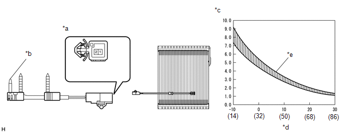
(1) Measure the resistance according to the value(s) in the table below.
|
*a |
Component without harness connected (No. 1 Cooler Thermistor) |
*b |
Sensing Portion |
|
*c |
Resistance (kΩ) |
*d |
Temperature (°C (°F)) |
|
*e |
Allowable Range |
- |
- |
Standard Resistance:
|
Tester Connection |
Condition |
Specified Condition |
|---|---|---|
|
1 - 2 |
-10°C (14°F) |
16.86 to 16.36 kΩ |
|
-5°C (23°F) |
12.86 to 12.54 kΩ |
|
|
0°C (32°F) |
9.89 to 9.70 kΩ |
|
|
5°C (41°F) |
7.70 to 7.52 kΩ |
|
|
10°C (50°F) |
6.04 to 5.89 kΩ |
|
|
15°C (59°F) |
4.77 to 4.65 kΩ |
|
|
20°C (68°F) |
3.81 to 3.69 kΩ |
|
|
25°C (77°F) |
3.05 to 2.95 kΩ |
|
|
30°C (86°F) |
2.46 to 2.37 kΩ |
If the resistance is not as specified, replace the No. 1 cooler thermistor.
NOTICE:
- Hold the sensor only by its connector. Touching the sensing portion may change the resistance value.
- When measuring, the sensor temperature must be the same as the ambient temperature.
HINT:
As the temperature increases, the resistance decreases (see the graph).
If the specified condition is not met, replace the No. 1 cooler thermistor.
 Removal
REMOVAL
CAUTION / NOTICE / HINT
The necessary procedures (adjustment, calibration, initialization or registration)
that must be performed after parts are removed and installed, or replaced during ...
 Installation
INSTALLATION
PROCEDURE
1. INSTALL NO. 1 COOLER THERMISTOR
(a) Install the No. 1 cooler thermistor.
HINT:
Install the No. 1 cooler thermistor in the same area as the one that was previously
inst ...
Other materials:
Toyota CH-R Service Manual > Window Defogger System: Rear Window Defogger System does not Operate
DESCRIPTION
When the rear window defogger switch on the air conditioning control assembly
is pressed, the operation signal is transmitted to the air conditioning amplifier
assembly via LIN communication. When the air conditioning amplifier assembly receives
the signal, it turns on the DEF rel ...
Toyota CH-R Service Manual > Vacuum Warning Switch: Components
COMPONENTS
ILLUSTRATION
*1
COWL BODY MOUNTING REINFORCEMENT LH
*2
COWL BODY MOUNTING REINFORCEMENT RH
*3
NO. 1 HEATER AIR DUCT SPLASH SHIELD SEAL
*4
OUTER COWL TOP PANEL SUB-ASSEMBLY
*5 ...
Toyota C-HR (AX20) 2023-2026 Owner's Manual
Toyota CH-R Owners Manual
- For safety and security
- Instrument cluster
- Operation of each component
- Driving
- Interior features
- Maintenance and care
- When trouble arises
- Vehicle specifications
- For owners
Toyota CH-R Service Manual
- Introduction
- Maintenance
- Audio / Video
- Cellular Communication
- Navigation / Multi Info Display
- Park Assist / Monitoring
- Brake (front)
- Brake (rear)
- Brake Control / Dynamic Control Systems
- Brake System (other)
- Parking Brake
- Axle And Differential
- Drive Shaft / Propeller Shaft
- K114 Cvt
- 3zr-fae Battery / Charging
- Networking
- Power Distribution
- Power Assist Systems
- Steering Column
- Steering Gear / Linkage
- Alignment / Handling Diagnosis
- Front Suspension
- Rear Suspension
- Tire / Wheel
- Tire Pressure Monitoring
- Door / Hatch
- Exterior Panels / Trim
- Horn
- Lighting (ext)
- Mirror (ext)
- Window / Glass
- Wiper / Washer
- Door Lock
- Heating / Air Conditioning
- Interior Panels / Trim
- Lighting (int)
- Meter / Gauge / Display
- Mirror (int)
- Power Outlets (int)
- Pre-collision
- Seat
- Seat Belt
- Supplemental Restraint Systems
- Theft Deterrent / Keyless Entry

0.0095