Toyota CH-R Service Manual: Installation
INSTALLATION
PROCEDURE
1. ADJUST COMPRESSOR OIL
|
(a) When replacing the compressor with pulley assembly with a new one, gradually discharge the refrigerant gas from the service valve. Then drain the following amount of oil from the new compressor with pulley assembly before installation, so that the amount of oil contained in it is the same as that in the cooler compressor with pulley assembly to be replaced. Standard: Standard: (The amount of oil inside a new cooler compressor with pulley assembly: 80 (+15) cc (2.71 (+0.507) fl.oz.)) - (The amount of oil remaining in the removed compressor with pulley assembly A) = (The amount of oil to be removed when replacing the cooler compressor with pulley assembly) HINT: A new cooler compressor with pulley assembly is filled with sufficient oil for the whole cycle. Therefore, it is necessary to drain residual oil from the condenser and cooling unit. Example: If A is 45 cc (1.52 fl.oz.). Since this time 80 cc (2.82fl.oz.) - 45 cc (1.52 fl.oz.) =35 cc (1.18 fl.oz.), drain 35 cc (1.18 fl.oz.) of the oil from the new cooler compressor with pulley assembly. NOTICE:
|
|
.png)
2. INSTALL COMPRESSOR WITH PULLEY ASSEMBLY
(a) Using an E8 "TORX" socket wrench, temporarily install the compressor with pulley assembly with the 2 stud bolts.
Torque:
9.8 N·m {100 kgf·cm, 87 in·lbf}
|
(b) Temporarily install the 2 bolts and 2 nuts. |
|
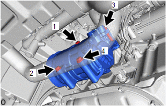
(c) Tighten the 2 bolts and 2 nuts to install the compressor with pulley assembly in the order as shown in the illustration.
Torque:
25 N·m {255 kgf·cm, 18 ft·lbf}
3. CONNECT SUCTION HOSE SUB-ASSEMBLY
(a) Remove the vinyl tape from the suction hose sub-assembly.
(b) Sufficiently apply compressor oil to a new O-ring and the fitting surface of the compressor with pulley assembly.
Compressor Oil:
VC100YF or equivalent
(c) Install the O-ring to the suction hose sub-assembly.
NOTICE:
Keep the O-ring and O-ring fitting surface free of foreign matter.
(d) Connect the suction hose sub-assembly to the compressor with pulley assembly with the bolt.
Torque:
9.8 N·m {100 kgf·cm, 87 in·lbf}
4. CONNECT DISCHARGE HOSE SUB-ASSEMBLY
(a) Remove the vinyl tape from the discharge hose sub-assembly.
(b) Apply sufficient compressor oil to a new O-rings and fitting surfaces of the cooler compressor with pulley assembly.
Compressor Oil:
VC100YF or equivalent
(c) Install the O-ring to the discharge hose sub-assembly.
NOTICE:
Keep the O-ring and O-ring fitting surface free of foreign matter.
(d) Connect the suction hose sub-assembly to the compressor with pulley assembly with the bolt.
Torque:
9.8 N·m {100 kgf·cm, 87 in·lbf}
(e) Connect the connector.
5. INSTALL FAN AND GENERATOR V BELT
Click here
.gif)
6. INSTALL NO. 1 ENGINE UNDER COVER
Click here
7. CHARGE AIR CONDITIONING SYSTEM WITH REFRIGERANT (for HFC-134a(R134a))
Click here
8. CHARGE AIR CONDITIONING SYSTEM WITH REFRIGERANT (for HFO-1234yf(R1234yf))
Click here
9. WARM UP ENGINE (for HFC-134a(R134a))
Click here
10. WARM UP ENGINE (for HFO-1234yf(R1234yf))
Click here
11. INSPECT FOR REFRIGERANT LEAK (for HFC-134a(R134a))
Click here
12. INSPECT FOR REFRIGERANT LEAK (for HFO-1234yf(R1234yf))
Click here
 Removal
REMOVAL
PROCEDURE
1. RECOVER REFRIGERANT FROM REFRIGERATION SYSTEM (for HFC-134a(R134a))
Click here
2. RECOVER REFRIGERANT FROM REFRIGERATION SYSTEM (for HFO-1234yf(R1234yf))
Click here
...
 Condenser
...
Other materials:
Toyota CH-R Service Manual > How To Troubleshoot Ecu Controlled Systems: Electronic Circuit Inspection Procedure
ELECTRONIC CIRCUIT INSPECTION PROCEDURE
BASIC INSPECTION
(a) WHEN MEASURING RESISTANCE OF ELECTRONIC PARTS
(1) Unless otherwise stated, all resistance measurements are standard values
measured at an ambient temperature of 20°C (68°F). Resistance measurements may be
inaccurate if measured at ...
Toyota CH-R Service Manual > Black Out Tape(for Rear Door): Removal
REMOVAL
CAUTION / NOTICE / HINT
The necessary procedures (adjustment, calibration, initialization, or registration)
that must be performed after parts are removed and installed, or replaced during
the black out tape removal/installation are shown below.
Necessary Procedure After Parts Removed ...
Toyota C-HR (AX20) 2023-2026 Owner's Manual
Toyota CH-R Owners Manual
- For safety and security
- Instrument cluster
- Operation of each component
- Driving
- Interior features
- Maintenance and care
- When trouble arises
- Vehicle specifications
- For owners
Toyota CH-R Service Manual
- Introduction
- Maintenance
- Audio / Video
- Cellular Communication
- Navigation / Multi Info Display
- Park Assist / Monitoring
- Brake (front)
- Brake (rear)
- Brake Control / Dynamic Control Systems
- Brake System (other)
- Parking Brake
- Axle And Differential
- Drive Shaft / Propeller Shaft
- K114 Cvt
- 3zr-fae Battery / Charging
- Networking
- Power Distribution
- Power Assist Systems
- Steering Column
- Steering Gear / Linkage
- Alignment / Handling Diagnosis
- Front Suspension
- Rear Suspension
- Tire / Wheel
- Tire Pressure Monitoring
- Door / Hatch
- Exterior Panels / Trim
- Horn
- Lighting (ext)
- Mirror (ext)
- Window / Glass
- Wiper / Washer
- Door Lock
- Heating / Air Conditioning
- Interior Panels / Trim
- Lighting (int)
- Meter / Gauge / Display
- Mirror (int)
- Power Outlets (int)
- Pre-collision
- Seat
- Seat Belt
- Supplemental Restraint Systems
- Theft Deterrent / Keyless Entry

0.008