Toyota CH-R Service Manual: Removal
REMOVAL
PROCEDURE
1. RECOVER REFRIGERANT FROM REFRIGERATION SYSTEM (for HFC-134a(R134a))
Click here
.gif)
2. RECOVER REFRIGERANT FROM REFRIGERATION SYSTEM (for HFO-1234yf(R1234yf))
Click here
3. REMOVE NO. 1 ENGINE UNDER COVER
Click here
4. REMOVE FAN AND GENERATOR V BELT
Click here
5. DISCONNECT DISCHARGE HOSE SUB-ASSEMBLY
|
(a) Disconnect the connector. |
|
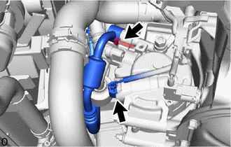
(b) Remove the bolt to disconnect the discharge hose sub-assembly from the compressor with pulley assembly.
(c) Remove the O-ring from the discharge hose sub-assembly.
NOTICE:
Seal the openings of the disconnected parts using vinyl tape to prevent moisture and foreign matter from entering them.
6. DISCONNECT SUCTION HOSE SUB-ASSEMBLY
|
(a) Remove the bolt to disconnect the suction hose sub-assembly from the compressor with pulley assembly. |
|
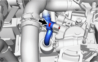
(b) Remove the O-ring from the suction hose sub-assembly.
NOTICE:
Seal the openings of the disconnected parts using vinyl tape to prevent moisture and foreign matter from entering them.
7. REMOVE COMPRESSOR WITH PULLEY ASSEMBLY
|
(a) Remove the 2 bolts and 2 nuts. |
|
.png)
|
(b) Using an E8 "TORX" socket wrench, remove the 2 stud bolts and compressor with pulley assembly. HINT: Remove the compressor with pulley assembly from the vehicle with the stud bolts remaining in the compressor with pulley assembly. |
|
.png)
 Inspection
INSPECTION
PROCEDURE
1. INSPECT COMPRESSOR WITH PULLEY ASSEMBLY
(a) Measure the resistance according to the value(s) in the table below.
Standard Resistance:
Test ...
 Installation
INSTALLATION
PROCEDURE
1. ADJUST COMPRESSOR OIL
(a) When replacing the compressor with pulley assembly with a new one,
gradually discharge the refrigerant gas from the service valve. ...
Other materials:
Toyota CH-R Service Manual > Key Reminder Warning System: Key Reminder Buzzer does not Sound
DESCRIPTION
The key reminder warning buzzer sounds when the driver door is opened while the
ignition switch is off or ACC. The key reminder warning buzzer is activated when
the main body ECU (multiplex network body ECU) sends an unlock warning switch signal
and driver door courtesy light swit ...
Toyota CH-R Service Manual > Front Door Speaker: Components
COMPONENTS
ILLUSTRATION
*A
for Driver Side
*B
for Front Passenger Side
*1
FRONT DOOR INSIDE HANDLE BEZEL PLUG
*2
FRONT DOOR TRIM BOARD SUB-ASSEMBLY
*3
FRONT NO. 1 SPEAKER ASS ...
Toyota C-HR (AX20) 2023-2026 Owner's Manual
Toyota CH-R Owners Manual
- For safety and security
- Instrument cluster
- Operation of each component
- Driving
- Interior features
- Maintenance and care
- When trouble arises
- Vehicle specifications
- For owners
Toyota CH-R Service Manual
- Introduction
- Maintenance
- Audio / Video
- Cellular Communication
- Navigation / Multi Info Display
- Park Assist / Monitoring
- Brake (front)
- Brake (rear)
- Brake Control / Dynamic Control Systems
- Brake System (other)
- Parking Brake
- Axle And Differential
- Drive Shaft / Propeller Shaft
- K114 Cvt
- 3zr-fae Battery / Charging
- Networking
- Power Distribution
- Power Assist Systems
- Steering Column
- Steering Gear / Linkage
- Alignment / Handling Diagnosis
- Front Suspension
- Rear Suspension
- Tire / Wheel
- Tire Pressure Monitoring
- Door / Hatch
- Exterior Panels / Trim
- Horn
- Lighting (ext)
- Mirror (ext)
- Window / Glass
- Wiper / Washer
- Door Lock
- Heating / Air Conditioning
- Interior Panels / Trim
- Lighting (int)
- Meter / Gauge / Display
- Mirror (int)
- Power Outlets (int)
- Pre-collision
- Seat
- Seat Belt
- Supplemental Restraint Systems
- Theft Deterrent / Keyless Entry

0.0096