Toyota CH-R Service Manual: Headlamp LH Circuit (B2439,B243A)
DESCRIPTION
A DTC is stored when the headlight ECU sub-assembly receives a light source malfunction signal from its respective headlight unit. The headlight ECU sub-assembly LH stores DTC B2439 or B243A.
|
DTC No. |
Detection Item |
DTC Detection Condition |
Trouble Area |
Note |
|---|---|---|---|---|
|
B2439 |
Headlamp LH Circuit |
headlight ECU sub-assembly LH light source malfunction |
|
- |
|
B243A |
Headlamp RH Circuit |
headlight ECU sub-assembly RH light source malfunction |
|
- |
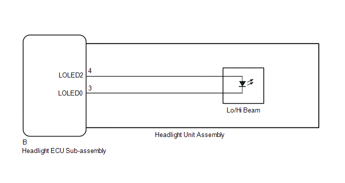
WIRING DIAGRAM
CAUTION / NOTICE / HINT
NOTICE:
If the headlight ECU sub-assembly LH has been replaced, it is necessary to synchronize the vehicle information and initialize the headlight ECU sub-assembly LH.
Click here
.gif)
PROCEDURE
|
1. |
CLEAR DTC |
(a) Clear the DTCs.
Click here
|
.gif)
|
2. |
CHECK FOR DTC |
(a) Turn the ignition switch to ON.
(b) Operate the light control switch to turn on the low beam headlights.
(c) Check for DTCs.
Click here
OK:
DTC B2439 and B243A are not output.
|
Result |
Proceed to |
|---|---|
|
OK |
A |
|
NG (DTC B2439 is output) |
B |
|
NG (DTC B243A is output) |
C |
| A | .gif) |
USE SIMULATION METHOD TO CHECK
|
| C | |
GO TO STEP 6 |
|
|
3. |
REPLACE HEADLIGHT UNIT ASSEMBLY LH |
(a) Replace the headlight unit assembly LH with a new or known good one.
- for Halogen Headlight: Click here
- for LED Headlight: Click here
|
|
4. |
CLEAR DTC |
(a) Clear the DTCs.
Click here
|
|
5. |
CHECK FOR DTC |
(a) Turn the ignition switch to ON.
(b) Operate the light control switch to turn on the low beam headlights.
(c) Check for DTCs.
Click here
OK:
DTC B2439 is not output.
| OK | |
END (HEADLIGHT UNIT ASSEMBLY LH WAS DEFECTIVE) |
| NG | |
REPLACE HEADLIGHT ECU SUB-ASSEMBLY LH |
|
6. |
REPLACE HEADLIGHT UNIT ASSEMBLY RH |
(a) Replace the headlight unit assembly RH with a new or known good one.
- for Halogen Headlight: Click here
- for LED Headlight: Click here
|
|
7. |
CLEAR DTC |
(a) Clear the DTCs.
Click here
|
|
8. |
CHECK FOR DTC |
(a) Turn the ignition switch to ON.
(b) Operate the light control switch to turn on the low beam headlights.
(c) Check for DTCs.
Click here
OK:
DTC B243A is not output.
| OK | |
END (HEADLIGHT UNIT ASSEMBLY RH WAS DEFECTIVE) |
| NG | |
REPLACE HEADLIGHT ECU SUB-ASSEMBLY RH |
 Lost Communication With Headlamp Control Module "B" (U0242)
DESCRIPTION
The headlight ECU sub-assembly LH stores this DTC when the headlight ECU sub-assembly
RH detects an internal malfunction or if a communication malfunction occurs between
headlight ECU ...
 Right Headlight ECU Malfunction (B242C,B242D)
DESCRIPTION
These DTCs are stored if the headlight ECU sub-assembly LH or RH detects an internal
malfunction. The headlight ECU sub-assembly LH stores DTC B242C or B242D.
DTC No.
...
Other materials:
Toyota CH-R Service Manual > Can Communication System: Check Bus 4 Line for Short to +B
DESCRIPTION
There may be a short circuit between one of the CAN bus lines and +B when no
resistance exists between terminal 22 (CA2H) of the central gateway ECU (network
gateway ECU) and terminal 16 (BAT) of the DLC3, or terminal 7 (CA2L) of the central
gateway ECU (network gateway ECU) and t ...
Toyota CH-R Service Manual > Side Airbag Sensor(for Center Pillar): Removal
REMOVAL
CAUTION / NOTICE / HINT
The necessary procedures (adjustment, calibration, initialization, or registration)
that must be performed after parts are removed, installed, or replaced during the
side airbag sensor removal/installation are shown below.
Necessary Procedure After Parts Remove ...
Toyota C-HR (AX20) 2023-2026 Owner's Manual
Toyota CH-R Owners Manual
- For safety and security
- Instrument cluster
- Operation of each component
- Driving
- Interior features
- Maintenance and care
- When trouble arises
- Vehicle specifications
- For owners
Toyota CH-R Service Manual
- Introduction
- Maintenance
- Audio / Video
- Cellular Communication
- Navigation / Multi Info Display
- Park Assist / Monitoring
- Brake (front)
- Brake (rear)
- Brake Control / Dynamic Control Systems
- Brake System (other)
- Parking Brake
- Axle And Differential
- Drive Shaft / Propeller Shaft
- K114 Cvt
- 3zr-fae Battery / Charging
- Networking
- Power Distribution
- Power Assist Systems
- Steering Column
- Steering Gear / Linkage
- Alignment / Handling Diagnosis
- Front Suspension
- Rear Suspension
- Tire / Wheel
- Tire Pressure Monitoring
- Door / Hatch
- Exterior Panels / Trim
- Horn
- Lighting (ext)
- Mirror (ext)
- Window / Glass
- Wiper / Washer
- Door Lock
- Heating / Air Conditioning
- Interior Panels / Trim
- Lighting (int)
- Meter / Gauge / Display
- Mirror (int)
- Power Outlets (int)
- Pre-collision
- Seat
- Seat Belt
- Supplemental Restraint Systems
- Theft Deterrent / Keyless Entry

0.0097