Toyota CH-R Service Manual: Evaporator Temperature Sensor Circuit (B1413)
DESCRIPTION
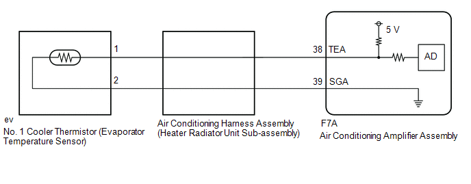
The No. 1 cooler thermistor (evaporator temperature sensor) is installed to the evaporator in the air conditioner unit to detect the temperature of the cooled air that has passed through the evaporator, which is used to control the air conditioning system. It sends signals to the air conditioning amplifier assembly. The resistance of the No. 1 cooler thermistor (evaporator temperature sensor) changes in accordance with the temperature of the cooled air that has passed through the evaporator. As the temperature decreases, the resistance increases. As the temperature increases, the resistance decreases.
The air conditioning amplifier assembly applies voltage (5 V) to the No. 1 cooler thermistor (evaporator temperature sensor) and reads voltage changes as the resistance of the No. 1 cooler thermistor (evaporator temperature sensor) changes. This sensor is used for frost prevention.
|
DTC No. |
Detection Item |
DTC Detection Condition |
Trouble Area |
Memory |
|---|---|---|---|---|
|
B1413 |
Evaporator Temperature Sensor Circuit |
Any of the following conditions is met:
|
|
Memorized (4 seconds or more)* |
- *: The air conditioning amplifier assembly stores this DTC if the malfunction has occurred for the period of time indicated in the brackets.
|
Vehicle Condition |
|||
|---|---|---|---|
|
Pattern 1 |
Pattern 2 |
||
|
Diagnosis Condition |
Ignition switch ON |
○ |
○ |
|
Malfunction Status |
Open in No. 1 cooler thermistor (evaporator temperature sensor) circuit |
○ |
- |
|
Short in No. 1 cooler thermistor (evaporator temperature sensor) circuit |
- |
○ |
|
|
Detection Time |
4 seconds or more |
4 seconds or more |
|
|
Number of Trips |
1 trip |
1 trip |
|
HINT:
DTC will be output when conditions for either of the patterns in the table above are met.
WIRING DIAGRAM
PROCEDURE
|
1. |
READ VALUE USING TECHSTREAM (EVAPORATOR FIN THERMISTOR) |
(a) Connect the Techstream to the DLC3.
(b) Turn the ignition switch ON.
(c) Turn the Techstream on.
(d) Enter the following menus: Body Electrical / Air Conditioner / Data List.
(e) Read the Data List according to the display on the Techstream.
Body Electrical > Air Conditioner > Data List|
Tester Display |
Measurement Item |
Range |
Normal Condition |
Diagnostic Note |
|---|---|---|---|---|
|
Evaporator Fin Thermistor |
No. 1 cooler thermistor (evaporator temperature sensor) |
Min.: -29.70°C (-21.46°F) Max.: 59.55°C (139.19°F) |
Actual evaporator temperature displayed |
- |
|
Tester Display |
|---|
|
Evaporator Fin Thermistor |
OK:
The display is as specified in the normal condition column.
|
Result |
Proceed to |
|---|---|
|
NG |
A |
|
OK (When troubleshooting according to Problem Symptoms Table) |
B |
|
OK (When troubleshooting according to the DTC) |
C |
| B | .gif) |
PROCEED TO NEXT SUSPECTED AREA SHOWN IN PROBLEM SYMPTOMS TABLE |
| C | |
GO TO STEP 4 |
|
.gif)
|
2. |
INSPECT NO. 1 COOLER THERMISTOR (EVAPORATOR TEMPERATURE SENSOR) |
(a) Remove the No. 1 cooler thermistor (evaporator temperature sensor).
Click here
.gif)
(b) Inspect the No. 1 cooler thermistor (evaporator temperature sensor).
Click here
| NG | |
REPLACE NO. 1 COOLER THERMISTOR (EVAPORATOR TEMPERATURE SENSOR) |
|
|
3. |
INSPECT AIR CONDITIONING HARNESS ASSEMBLY (HEATER RADIATOR UNIT SUB-ASSEMBLY) |
(a) Remove the air conditioning harness assembly (heater radiator unit sub-assembly)
Click here
|
(b) Measure the resistance according to the value(s) in the table below. Standard Resistance:
|
|
| OK | |
REPLACE AIR CONDITIONING AMPLIFIER ASSEMBLY |
| NG | |
REPLACE AIR CONDITIONING HARNESS ASSEMBLY (HEATER RADIATOR UNIT SUB-ASSEMBLY) |
|
4. |
CHECK FOR DTC |
(a) Clear the DTCs.
Click here
(b) Check for DTCs.
Click here
|
Result |
Proceed to |
|---|---|
|
DTCs are not output |
A |
|
DTCs are output |
B |
| A | |
USE SIMULATION METHOD TO CHECK |
| B | |
REPLACE AIR CONDITIONING AMPLIFIER ASSEMBLY |
 Room Temperature Sensor Circuit (B1411)
DESCRIPTION
The cooler thermistor (room temperature sensor) is installed in the instrument
panel to detect the cabin temperature, which is used to control the air conditioning
system. The resista ...
 Ambient Temperature Sensor Circuit (B1412)
DESCRIPTION
The thermistor assembly is installed in front of the cooler condenser assembly
to detect the ambient temperature, which is used to control the air conditioning
system. This sensor is ...
Other materials:
Toyota CH-R Service Manual > Power Window Regulator Motor(for Front Door): Removal
REMOVAL
CAUTION / NOTICE / HINT
The necessary procedures (adjustment, calibration, initialization or registration)
that must be performed after parts are removed and installed, or replaced during
the power window regulator motor removal/installation are shown below.
Necessary Procedures After ...
Toyota CH-R Service Manual > Tire Pressure Monitoring: Tire Pressure Warning Receiver
Components
COMPONENTS
ILLUSTRATION
*A
for Type A
*B
for Type B
*1
TIRE PRESSURE WARNING ECU AND RECEIVER
-
-
N*m (kgf*cm, ft.*lbf): Specified torque
-
...
Toyota C-HR (AX20) 2023-2026 Owner's Manual
Toyota CH-R Owners Manual
- For safety and security
- Instrument cluster
- Operation of each component
- Driving
- Interior features
- Maintenance and care
- When trouble arises
- Vehicle specifications
- For owners
Toyota CH-R Service Manual
- Introduction
- Maintenance
- Audio / Video
- Cellular Communication
- Navigation / Multi Info Display
- Park Assist / Monitoring
- Brake (front)
- Brake (rear)
- Brake Control / Dynamic Control Systems
- Brake System (other)
- Parking Brake
- Axle And Differential
- Drive Shaft / Propeller Shaft
- K114 Cvt
- 3zr-fae Battery / Charging
- Networking
- Power Distribution
- Power Assist Systems
- Steering Column
- Steering Gear / Linkage
- Alignment / Handling Diagnosis
- Front Suspension
- Rear Suspension
- Tire / Wheel
- Tire Pressure Monitoring
- Door / Hatch
- Exterior Panels / Trim
- Horn
- Lighting (ext)
- Mirror (ext)
- Window / Glass
- Wiper / Washer
- Door Lock
- Heating / Air Conditioning
- Interior Panels / Trim
- Lighting (int)
- Meter / Gauge / Display
- Mirror (int)
- Power Outlets (int)
- Pre-collision
- Seat
- Seat Belt
- Supplemental Restraint Systems
- Theft Deterrent / Keyless Entry

0.0091