Toyota CH-R Service Manual: Disassembly
DISASSEMBLY
PROCEDURE
1. PRECAUTION
NOTICE:
Make sure to perform initialization after replacing the No. 1 blower damper servo sub-assembly. If initialization is not performed, the air conditioner unit assembly will not perform properly as the air conditioning amplifier assembly will not be able to recognize the position of the No. 1 blower damper servo sub-assembly.
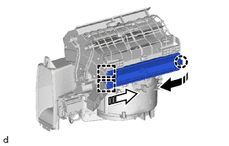
2. REMOVE AIR FILTER COVER PLATE
(a) Disengage the claw and guides to remove the air filter cover plate as shown in the illustration.
.png) |
Remove in this Direction (1) |
.png) |
Remove in this Direction (2) |
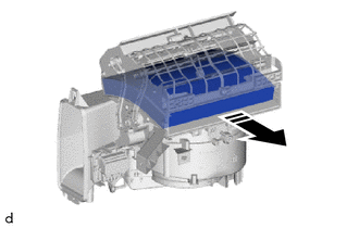
3. REMOVE CLEAN AIR FILTER
(a) Remove the clean air filter as shown in the illustration.
|
|
Remove in this Direction |
4. REMOVE BLOWER MOTOR WITH FAN SUB-ASSEMBLY (for Single Type)
|
(a) Disconnect the connector. |
|
(b) Remove the 3 screws and blower motor with fan sub-assembly.
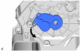
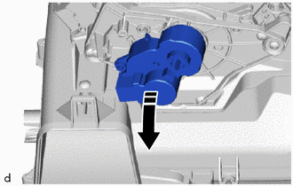
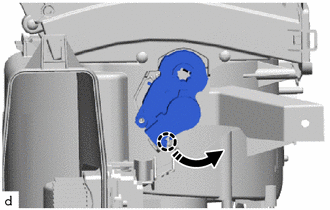
5. REMOVE NO. 1 BLOWER DAMPER SERVO SUB-ASSEMBLY (for Dual Type)
(a) Turn the No. 1 blower damper servo sub-assembly to disengage the claw as shown in the illustration.
|
|
Remove in this Direction |
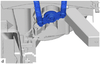
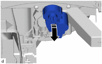
(b) Remove the No. 1 blower damper servo sub-assembly as shown in the illustration.
|
|
Remove in this Direction |
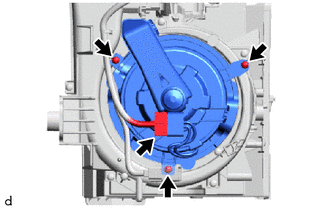
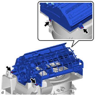
6. REMOVE AIR FILTER SUB-ASSEMBLY (for Dual Type)
|
(a) Remove the 4 screws and the air filter sub-assembly. |
|
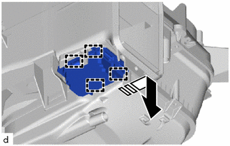
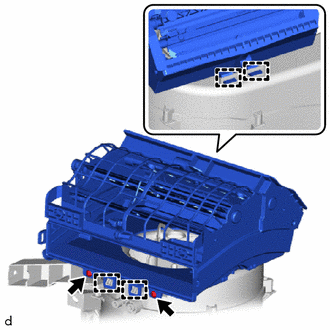
7. REMOVE BLOWER RESISTOR (for Dual Type)
(a) Disengage the guides and remove the blower resistor as shown in the illustration.
|
|
Remove in this Direction |
8. REMOVE NO. 1 BLOWER DAMPER SERVO SUB-ASSEMBLY (for Single Type)
|
(a) Disconnect the damper servo link. |
|
(b) Turn the No. 1 blower damper servo sub-assembly to disengage the claw as shown in the illustration.
|
|
Remove in this Direction |
(c) Remove the No. 1 blower damper servo sub-assembly as shown in the illustration.
|
|
Remove in this Direction |
9. REMOVE AIR FILTER SUB-ASSEMBLY (for Single Type)
|
(a) Remove the 2 screws. |
|
(b) Disengage the guides to remove the air filter sub-assembly.
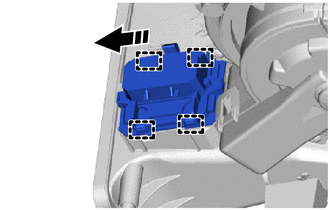
10. REMOVE BLOWER RESISTOR (for Single Type)
(a) Disengage the guides and remove the blower resistor as shown in the illustration.
|
|
Remove in this Direction |
 Removal
REMOVAL
CAUTION / NOTICE / HINT
The necessary procedures (adjustment, calibration, initialization, or registration)
that must be performed after parts are removed, installed, or replaced during th ...
 Installation
INSTALLATION
PROCEDURE
1. INSTALL BLOWER ASSEMBLY
(a) Engage the guides to install the air conditioning radiator assembly.
(b) Install th ...
Other materials:
Toyota CH-R Service Manual > Radio Antenna Cord: Components
COMPONENTS
ILLUSTRATION
*1
ANTENNA CORD SUB-ASSEMBLY
*2
NO. 3 HEATER TO REGISTER DUCT SUB-ASSEMBLY
ILLUSTRATION
*A
Type A
*B
Type B
*1
NO. 2 ANTENNA CORD SUB-ASSEMBLY
...
Toyota CH-R Service Manual > Audio And Visual System(for Radio Receiver Type): Microphone Circuit between Microphone and Radio Receiver
DESCRIPTION
The radio receiver assembly and map light assembly (telephone microphone assembly)
are connected to each other using the microphone connection detection signal lines.
Using this circuit, the radio receiver assembly sends power to the map light
assembly (telephone microphone assembl ...
Toyota C-HR (AX20) 2023-2026 Owner's Manual
Toyota CH-R Owners Manual
- For safety and security
- Instrument cluster
- Operation of each component
- Driving
- Interior features
- Maintenance and care
- When trouble arises
- Vehicle specifications
- For owners
Toyota CH-R Service Manual
- Introduction
- Maintenance
- Audio / Video
- Cellular Communication
- Navigation / Multi Info Display
- Park Assist / Monitoring
- Brake (front)
- Brake (rear)
- Brake Control / Dynamic Control Systems
- Brake System (other)
- Parking Brake
- Axle And Differential
- Drive Shaft / Propeller Shaft
- K114 Cvt
- 3zr-fae Battery / Charging
- Networking
- Power Distribution
- Power Assist Systems
- Steering Column
- Steering Gear / Linkage
- Alignment / Handling Diagnosis
- Front Suspension
- Rear Suspension
- Tire / Wheel
- Tire Pressure Monitoring
- Door / Hatch
- Exterior Panels / Trim
- Horn
- Lighting (ext)
- Mirror (ext)
- Window / Glass
- Wiper / Washer
- Door Lock
- Heating / Air Conditioning
- Interior Panels / Trim
- Lighting (int)
- Meter / Gauge / Display
- Mirror (int)
- Power Outlets (int)
- Pre-collision
- Seat
- Seat Belt
- Supplemental Restraint Systems
- Theft Deterrent / Keyless Entry

0.0107