Toyota CH-R Service Manual: Communication Malfunction (Bus Ic) (B1497)
DESCRIPTION
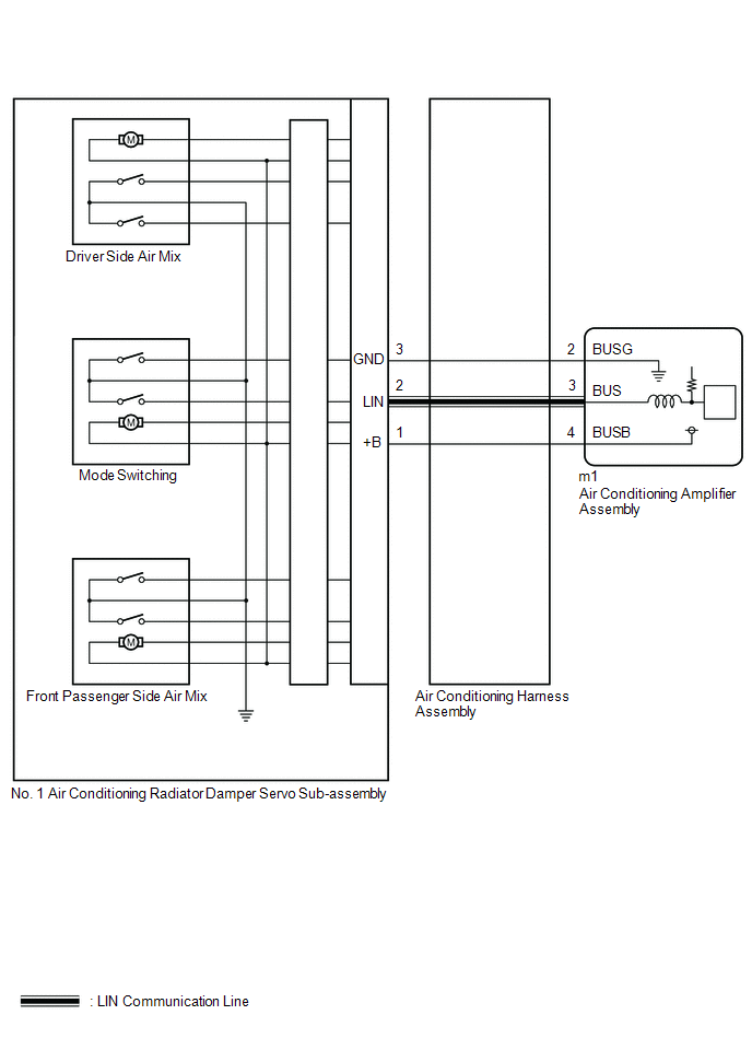
The air conditioning harness assembly connects the air conditioning amplifier assembly and the servo motors. The air conditioning amplifier assembly supplies power and sends operation instructions to each servo motor through the air conditioning harness assembly. Each servo motor sends damper position information to the air conditioning amplifier assembly.
|
DTC No. |
Detection Item |
DTC Detection Condition |
Trouble Area |
Memory |
|---|---|---|---|---|
|
B1497 |
Communication Malfunction (Bus Ic) |
Any of the following conditions is met:
|
|
Memorized (10 seconds or more)* |
- *: The air conditioning amplifier assembly stores this DTC if the malfunction has occurred for the period of time indicated in the brackets.
|
Vehicle Condition |
|||
|---|---|---|---|
|
Pattern 1 |
Pattern 2 |
||
|
Diagnosis Condition |
Ignition switch ON |
○ |
○ |
|
Malfunction Status |
Error in communication line |
○ |
- |
|
Open in communication line |
- |
○ |
|
|
Detection Time |
10 seconds or more |
10 seconds or more |
|
|
Number of Trips |
1 trip |
1 trip |
|
HINT:
DTC will be output when conditions for either of the patterns in the table above are met.
WIRING DIAGRAM
PROCEDURE
|
1. |
PERFORM ACTIVE TEST USING TECHSTREAM |
(a) Connect the Techstream to the DLC3.
(b) Turn the ignition switch ON.
(c) Turn the Techstream on.
(d) Enter the following menus: Body Electrical / Air Conditioner / Active Test.
(e) Perform the Active Test according to the display on the Techstream.
Body Electrical > Air Conditioner > Active Test|
Tester Display |
Measurement Item |
Control Range |
Diagnostic Note |
|---|---|---|---|
|
Air Mix Servo Targ Pulse(D) |
No. 1 air conditioning radiator damper servo sub-assembly (driver side air mix) pulse |
Min.: 128 Max.: 383 |
Operates between 255 to 347 pulses |
|
Tester Display |
|---|
|
Air Mix Servo Targ Pulse(D) |
OK:
No. 1 air conditioning radiator damper servo motor operates smoothly.
|
Result |
Proceed to |
|---|---|
|
No. 1 air conditioning radiator damper servo motors are malfunctioning |
A |
|
No. 1 air conditioning radiator damper servo motors is normal |
B |
| B | .gif) |
GO TO STEP 4 |
|
.gif)
|
2. |
INSPECT AIR CONDITIONING HARNESS ASSEMBLY (AIR CONDITIONING AMPLIFIER ASSEMBLY - NO. 1 AIR CONDITIONING RADIATOR DAMPER SERVO SUB-ASSEMBLY) |
NOTICE:
When inspecting the air conditioning amplifier assembly, do not bring the tester probes too close to each other as a short circuit may occur.
(a) Disconnect the m1 air conditioning amplifier assembly connector.
(b) Disconnect the No. 1 air conditioning radiator damper servo sub-assembly connector.
(c) Measure the resistance according to the value(s) in the table below.
Standard Resistance:
|
Tester Connection |
Condition |
Specified Condition |
|---|---|---|
|
m1-2 (BUS G) - Body ground |
Always |
Below 1 Ω |
|
m1-3 (BUS) - 2 (LIN) |
Always |
Below 1 Ω |
|
m1-4 (BUSB) - 1 (+B) |
Always |
Below 1 Ω |
| NG | |
REPLACE AIR CONDITIONING HARNESS ASSEMBLY |
|
|
3. |
INSPECT AIR CONDITIONING AMPLIFIER ASSEMBLY |
NOTICE:
When inspecting the air conditioning amplifier assembly, do not bring the tester probes too close to each other as a short circuit may occur.
(a) Turn the ignition switch ON.
|
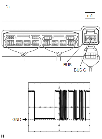
(b) Connect an oscilloscope to terminals m1-2 (BUS G) and m1-3 (BUS) of the air conditioning amplifier assembly and check the waveform. OK: Waveform is similar to that shown in the illustration. HINT: The waveform varies with the blower speed.
|
|
| OK | |
REPLACE NO. 1 AIR CONDITIONING RADIATOR DAMPER SERVO SUB-ASSEMBLY |
| NG | |
REPLACE AIR CONDITIONING AMPLIFIER ASSEMBLY |
|
4. |
CHECK FOR DTC* |
(a) Clear the DTCs.
Click here
.gif)
(b) Check for DTCs.
Click here
|
Result |
Proceed to |
|---|---|
|
DTCs are not output |
A |
|
DTCs are output |
B |
| A | |
USE SIMULATION METHOD TO CHECK |
| B | |
REPLACE AIR CONDITIONING AMPLIFIER ASSEMBLY |
 Refrigerant Shortage (B14B8)
DESCRIPTION
This DTC is stored if the amount of refrigerant in the air conditioning system
is insufficient.
The air conditioning amplifier assembly receives the ambient temperature signal,
refri ...
 Compressor Solenoid Circuit (B1451)
DESCRIPTION
In this circuit, the cooler compressor assembly (compressor solenoid) receives
a refrigerant compression demand signal from the air conditioning amplifier assembly.
Based on this signa ...
Other materials:
Toyota CH-R Owners Manual > Operating the lights and wipers: Headlight switch
The headlights can be operated manually or automatically.
Operating instructions
Turning the
switch
turns on the lights as follows:
For U.S.A.
The headlights, side marker, parking lights, daytime running lights and so on
turn on and off automatically.
(When the engine switch ...
Toyota CH-R Service Manual > Meter / Gauge System: Fuel Sender Open Detected (B1500)
DESCRIPTION
This DTC is stored when the combination meter assembly detects a fuel sender
gauge assembly malfunction via a direct line.
DTC No.
Detection Item
DTC Detection Condition
Trouble Area
Memory
B1500
Fuel ...
Toyota C-HR (AX20) 2023-2026 Owner's Manual
Toyota CH-R Owners Manual
- For safety and security
- Instrument cluster
- Operation of each component
- Driving
- Interior features
- Maintenance and care
- When trouble arises
- Vehicle specifications
- For owners
Toyota CH-R Service Manual
- Introduction
- Maintenance
- Audio / Video
- Cellular Communication
- Navigation / Multi Info Display
- Park Assist / Monitoring
- Brake (front)
- Brake (rear)
- Brake Control / Dynamic Control Systems
- Brake System (other)
- Parking Brake
- Axle And Differential
- Drive Shaft / Propeller Shaft
- K114 Cvt
- 3zr-fae Battery / Charging
- Networking
- Power Distribution
- Power Assist Systems
- Steering Column
- Steering Gear / Linkage
- Alignment / Handling Diagnosis
- Front Suspension
- Rear Suspension
- Tire / Wheel
- Tire Pressure Monitoring
- Door / Hatch
- Exterior Panels / Trim
- Horn
- Lighting (ext)
- Mirror (ext)
- Window / Glass
- Wiper / Washer
- Door Lock
- Heating / Air Conditioning
- Interior Panels / Trim
- Lighting (int)
- Meter / Gauge / Display
- Mirror (int)
- Power Outlets (int)
- Pre-collision
- Seat
- Seat Belt
- Supplemental Restraint Systems
- Theft Deterrent / Keyless Entry

0.0113