Toyota CH-R Service Manual: Compressor Solenoid Circuit (B1451)
DESCRIPTION
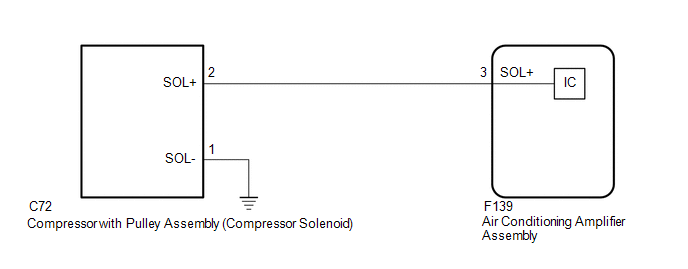
In this circuit, the cooler compressor assembly (compressor solenoid) receives a refrigerant compression demand signal from the air conditioning amplifier assembly.
Based on this signal, the cooler compressor assembly (compressor solenoid) changes the amount of compressor output.
|
DTC No. |
Detection Item |
DTC Detection Condition |
Trouble Area |
Memory |
|---|---|---|---|---|
|
B1451 |
Compressor Solenoid Circuit |
Any of the following conditions is met:
|
|
- |
|
Vehicle Condition |
|||
|---|---|---|---|
|
Pattern 1 |
Pattern 2 |
||
|
Diagnosis Condition |
Ignition switch ON |
○ |
○ |
|
Malfunction Status |
Open in compressor solenoid circuit |
○ |
- |
|
Short in compressor solenoid circuit |
- |
○ |
|
|
Detection Time |
30 seconds or more |
30 seconds or more |
|
|
Number of Trips |
1 trip |
1 trip |
|
HINT:
The air conditioning amplifier assembly stores this DTC if the malfunction has occurred for the period of time indicated in the brackets.
WIRING DIAGRAM
PROCEDURE
|
1. |
INSPECT COMPRESSOR WITH PULLEY ASSEMBLY (COMPRESSOR SOLENOID) |
|
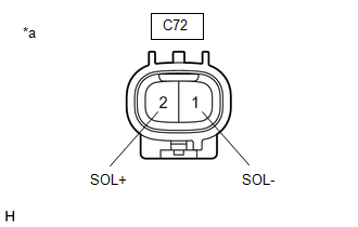
(a) Disconnect the cooler compressor assembly (compressor solenoid) connector. |
|
(b) Measure the resistance according to the value(s) in the table below.
Standard Resistance:
|
Tester Connection |
Condition |
Specified Condition |
|---|---|---|
|
1 (SOL-) - 2 (SOL+) |
25°C (77°F) |
10.1 to 11.1 Ω |
| NG | .gif) |
REPLACE COMPRESSOR WITH PULLEY ASSEMBLY (COMPRESSOR SOLENOID) |
|
.gif)
|
2. |
CHECK HARNESS AND CONNECTOR (COOLER COMPRESSOR ASSEMBLY (COMPRESSOR SOLENOID) - BODY GROUND) |
(a) Measure the resistance according to the value(s) in the table below.
Standard Resistance:
|
Tester Connection |
Condition |
Specified Condition |
|---|---|---|
|
C72-1 (SOL-) - Body ground |
Always |
Below 1 Ω |
| NG | |
REPAIR OR REPLACE HARNESS OR CONNECTOR |
|
|
3. |
CHECK HARNESS AND CONNECTOR (COOLER COMPRESSOR ASSEMBLY (COMPRESSOR SOLENOID) - AIR CONDITIONING AMPLIFIER ASSEMBLY) |
(a) Disconnect the F139 air conditioning amplifier assembly connector.
(b) Measure the resistance according to the value(s) in the table below.
Standard Resistance:
|
Tester Connection |
Condition |
Specified Condition |
|---|---|---|
|
C72-2 (SOL+) - F139-3 (SOL+) |
Always |
Below 1 Ω |
|
C72-2 (SOL+) or F139-3 (SOL+) - Body ground |
Always |
10 kΩ or higher |
|
Result |
Proceed to |
|---|---|
|
NG |
A |
|
OK (When troubleshooting according to the Problem Symptoms Table) |
B |
|
OK (When troubleshooting according to the DTC) |
C |
| A | |
REPAIR OR REPLACE HARNESS OR CONNECTOR |
| B | |
PROCEED TO NEXT SUSPECTED AREA SHOWN IN PROBLEM SYMPTOMS TABLE |
|
|
4. |
CHECK FOR DTC |
(a) Clear the DTCs.
Click here
.gif)
(b) Check for DTCs.
Click here
|
Result |
Proceed to |
|---|---|
|
DTCs are not output |
A |
|
DTCs are output |
B |
| A | |
USE SIMULATION METHOD TO CHECK |
| B | |
REPLACE AIR CONDITIONING AMPLIFIER ASSEMBLY |
 Communication Malfunction (Bus Ic) (B1497)
DESCRIPTION
The air conditioning harness assembly connects the air conditioning amplifier
assembly and the servo motors. The air conditioning amplifier assembly supplies
power and sends operation ...
 Evaporator Temperature Sensor Circuit (B1413)
DESCRIPTION
The No. 1 cooler thermistor (evaporator temperature sensor) is installed to the
evaporator in the air conditioner unit to detect the temperature of the cooled air
that has passed thro ...
Other materials:
Toyota CH-R Service Manual > Airbag System: TC and CG Terminal Circuit
DESCRIPTION
DTC output mode is set by connecting terminals TC and CG of the DLC3.
DTCs are displayed by blinking of the SRS warning light.
HINT:
When multiple warning lights in the combination meter blink continuously,
a short to ground in the wiring or an ECU connected to terminal T ...
Toyota CH-R Service Manual > Airbag System: Short in Rear Side Squib RH Circuit (B1850/62-B1853/62)
DESCRIPTION
The rear side squib RH circuit consists of the airbag sensor assembly and rear
seat airbag RH
The airbag sensor assembly uses this circuit to deploy the airbag when deployment
conditions are met.
These DTCs are stored when a malfunction is detected in the rear side squib RH
circ ...
Toyota C-HR (AX20) 2023-2026 Owner's Manual
Toyota CH-R Owners Manual
- For safety and security
- Instrument cluster
- Operation of each component
- Driving
- Interior features
- Maintenance and care
- When trouble arises
- Vehicle specifications
- For owners
Toyota CH-R Service Manual
- Introduction
- Maintenance
- Audio / Video
- Cellular Communication
- Navigation / Multi Info Display
- Park Assist / Monitoring
- Brake (front)
- Brake (rear)
- Brake Control / Dynamic Control Systems
- Brake System (other)
- Parking Brake
- Axle And Differential
- Drive Shaft / Propeller Shaft
- K114 Cvt
- 3zr-fae Battery / Charging
- Networking
- Power Distribution
- Power Assist Systems
- Steering Column
- Steering Gear / Linkage
- Alignment / Handling Diagnosis
- Front Suspension
- Rear Suspension
- Tire / Wheel
- Tire Pressure Monitoring
- Door / Hatch
- Exterior Panels / Trim
- Horn
- Lighting (ext)
- Mirror (ext)
- Window / Glass
- Wiper / Washer
- Door Lock
- Heating / Air Conditioning
- Interior Panels / Trim
- Lighting (int)
- Meter / Gauge / Display
- Mirror (int)
- Power Outlets (int)
- Pre-collision
- Seat
- Seat Belt
- Supplemental Restraint Systems
- Theft Deterrent / Keyless Entry

0.0088