Toyota CH-R Service Manual: Child Restraint Seat Anchor Bracket
Components
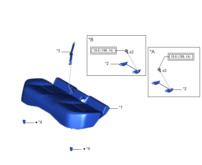
COMPONENTS
ILLUSTRATION
|
*A |
for LH Side |
*B |
for RH Side |
|
*1 |
BENCH TYPE REAR SEAT CUSHION ASSEMBLY |
*2 |
CROSS ANCHOR BRACKET SUB-ASSEMBLY |
|
*3 |
REAR CENTER SEAT OUTER BELT ASSEMBLY |
*4 |
REAR SEAT CUSHION LOCK HOOK |
.png) |
Tightening torque for "Major areas involving basic vehicle performance such as moving/turning/stopping" : N*m (kgf*cm, ft.*lbf) |
● |
Non-reusable part |
Removal
REMOVAL
PROCEDURE
1. DISCONNECT REAR CENTER SEAT OUTER BELT ASSEMBLY
Click here .gif)
2. REMOVE BENCH TYPE REAR SEAT CUSHION ASSEMBLY
Click here
3. REMOVE REAR SEAT CUSHION LOCK HOOK
Click here
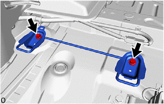
4. REMOVE CROSS ANCHOR BRACKET SUB-ASSEMBLY (for LH Side)
|
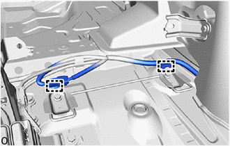
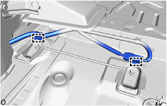
(a) Disengage the clamps. |
|
|
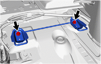
(b) Remove the 2 bolts and cross anchor bracket sub-assembly. |
|
5. REMOVE CROSS ANCHOR BRACKET SUB-ASSEMBLY (for RH Side)
|
(a) Disengage the clamps. |
|
|
(b) Remove the 2 bolts and cross anchor bracket sub-assembly. |
|
Installation
INSTALLATION
PROCEDURE
1. INSTALL CROSS ANCHOR BRACKET SUB-ASSEMBLY (for LH Side)
|
(a) Temporarily install the cross anchor bracket sub-assembly with the 2 bolts. |
|
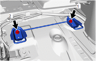
(b) Tighten the 2 bolts in the order shown in the illustration.
Torque:
19.5 N·m {199 kgf·cm, 14 ft·lbf}
|
(c) Engage the clamps. |
|
.png)
2. INSTALL CROSS ANCHOR BRACKET SUB-ASSEMBLY (for RH Side)
|
(a) Temporarily install the cross anchor bracket sub-assembly with the 2 bolts. |
|

(b) Tighten the 2 bolts in the order shown in the illustration.
Torque:
19.5 N·m {199 kgf·cm, 14 ft·lbf}
|
(c) Engage the clamps. |
|
.png)
3. INSTALL REAR SEAT CUSHION LOCK HOOK
Click here .gif)
4. INSTALL BENCH TYPE REAR SEAT CUSHION ASSEMBLY
Click here
5. CONNECT REAR CENTER SEAT OUTER BELT ASSEMBLY
Click here
 Seat Belt
...

Other materials:
Toyota CH-R Service Manual > K114 Cvt: Shift Lever Knob
Components
COMPONENTS
ILLUSTRATION
*1
SHIFT LEVER CAP
*2
SHIFT LEVER KNOB SUB-ASSEMBLY
Removal
REMOVAL
PROCEDURE
1. REMOVE SHIFT LEVER CAP
Click here
2. REMOVE SHIFT LEVER KNOB SUB-ASSEMBLY
Remove in this ...
Toyota CH-R Service Manual > Front Brake: Installation
INSTALLATION
CAUTION / NOTICE / HINT
NOTICE:
Immediately after installing the brake pads, the braking performance
may be reduced. Always perform a road test in a safe place while paying
attention to the surroundings.
After replacing the front disc brake pads, always perform a ...
Toyota C-HR (AX20) 2023-2026 Owner's Manual
Toyota CH-R Owners Manual
- For safety and security
- Instrument cluster
- Operation of each component
- Driving
- Interior features
- Maintenance and care
- When trouble arises
- Vehicle specifications
- For owners
Toyota CH-R Service Manual
- Introduction
- Maintenance
- Audio / Video
- Cellular Communication
- Navigation / Multi Info Display
- Park Assist / Monitoring
- Brake (front)
- Brake (rear)
- Brake Control / Dynamic Control Systems
- Brake System (other)
- Parking Brake
- Axle And Differential
- Drive Shaft / Propeller Shaft
- K114 Cvt
- 3zr-fae Battery / Charging
- Networking
- Power Distribution
- Power Assist Systems
- Steering Column
- Steering Gear / Linkage
- Alignment / Handling Diagnosis
- Front Suspension
- Rear Suspension
- Tire / Wheel
- Tire Pressure Monitoring
- Door / Hatch
- Exterior Panels / Trim
- Horn
- Lighting (ext)
- Mirror (ext)
- Window / Glass
- Wiper / Washer
- Door Lock
- Heating / Air Conditioning
- Interior Panels / Trim
- Lighting (int)
- Meter / Gauge / Display
- Mirror (int)
- Power Outlets (int)
- Pre-collision
- Seat
- Seat Belt
- Supplemental Restraint Systems
- Theft Deterrent / Keyless Entry

0.0071