Toyota CH-R Service Manual: Refrigerant Shortage (B14B8)
DESCRIPTION
This DTC is stored if the amount of refrigerant in the air conditioning system is insufficient.
The air conditioning amplifier assembly receives the ambient temperature signal, refrigerant pressure signal, etc. from various sensors.
Based on these signals, the air conditioning amplifier assembly detects the amount of refrigerant.
The A/C switch indicator is turned off and the air conditioning system is stopped if the amount of refrigerant is insufficient.
|
DTC No. |
Detection Item |
DTC Detection Condition |
Trouble Area |
Memory |
|---|---|---|---|---|
|
B14B8 |
Refrigerant Shortage |
When following condition is detected in refrigerant shortage check in normal operation: Amount of refrigerant is insufficient |
|
Memorized (15 min. or more)* |
- *: The air conditioning amplifier assembly stores this DTC if the malfunction has occurred for the period of time indicated in the brackets.
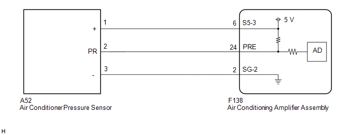
WIRING DIAGRAM
PROCEDURE
|
1. |
CHECK REFRIGERANT PRESSURE |
(a) Connect the Techstream to the DLC3.
(b) Turn the ignition switch to ON.
(c) Turn the Techstream on.
(d) Enter the following menus: Body Electrical / Air Conditioner / Data List.
(e) Read the Data List according to the display on the Techstream.
Body Electrical > Air Conditioner > Data List|
Tester Display |
Measurement Item |
Range |
Normal Condition |
Diagnostic Note |
|---|---|---|---|---|
|
Regulator Pressure Sensor |
Air conditioner pressure sensor |
Min.: -456.6 kPaG Max.: 3294.3 kPaG |
Actual refrigerant pressure displayed |
- |
|
Tester Display |
|---|
|
Regulator Pressure Sensor |
(f) Install a manifold gauge set.
Click here
.gif)
(g) Read the manifold gauge pressure when the following conditions are met.
(1) Prepare the vehicle according to the table below.
Measurement Condition:|
Item |
Condition |
|---|---|
|
Vehicle doors |
Fully open |
|
Temperature setting |
MAX COLD |
|
Blower speed |
HI |
|
A/C switch |
On |
|
Recirculation/fresh switch |
RECIRCULATION |
|
Interior temperature |
25 to 35°C (77 to 95°F) |
Standard Pressure:
Low pressure side
150 to 250 kPa (1.5 to 2.5 kgf/cm2, 22 to 36 psi)
High pressure side
1370 to 1570 kPa (14 to 16 kgf/cm2, 199 to 228 psi)
(h) Compare the values displayed in the Data List and on the manifold gauge.
OK:
The values displayed in the Data List and on the manifold gauge match.
| OK | .gif) |
CHECK REFRIGERANT PRESSURE |
|
.gif)
|
2. |
CHECK HARNESS AND CONNECTOR (POWER SOURCE CIRCUIT) |
|
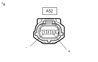
(a) Disconnect the air conditioner pressure sensor connector. |
|
(b) Measure the voltage according to the value(s) in the table below.
Standard Voltage:
|
Tester Connection |
Switch Condition |
Specified Condition |
|---|---|---|
|
A52-3 (+) - A52-1 (-) |
Ignition switch to ON |
4.75 to 5.25 V |
| NG | |
GO TO STEP 7 |
|
|
3. |
CHECK HARNESS AND CONNECTOR (AIR CONDITIONER PRESSURE SENSOR - BODY GROUND) |
(a) Measure the resistance according to the value(s) in the table below.
Standard Resistance:
|
Tester Connection |
Condition |
Specified Condition |
|---|---|---|
|
A52-1 (-) - Body ground |
Always |
Below 1 Ω |
| NG | |
GO TO STEP 6 |
|
|
4. |
CHECK HARNESS AND CONNECTOR (AIR CONDITIONING AMPLIFIER ASSEMBLY - AIR CONDITIONER PRESSURE SENSOR) |
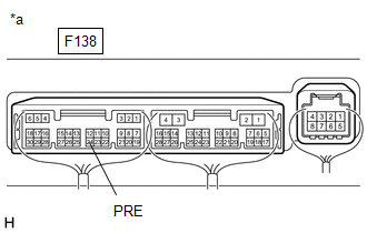
(a) Disconnect the F138 air conditioning amplifier assembly connector.
(b) Measure the resistance according to the value(s) in the table below.
Standard Resistance:
|
Tester Connection |
Condition |
Specified Condition |
|---|---|---|
|
A52-2 (PR) - F138-24 (PRE) |
Always |
Below 1 Ω |
|
A52-2 (PR) or F138-24 (PRE) - Body ground |
Always |
10 kΩ or higher |
| NG | |
REPAIR OR REPLACE HARNESS OR CONNECTOR |
|
|
5. |
INSPECT AIR CONDITIONER PRESSURE SENSOR (SENSOR SIGNAL CIRCUIT) |
(a) Measure the voltage when the following conditions are met.
Measurement Condition:|
Item |
Condition |
|---|---|
|
Vehicle doors |
Fully open |
|
Temperature setting |
MAX COLD |
|
Blower speed |
HI |
|
A/C switch |
On |
|
Recirculation/fresh switch |
RECIRCULATION |
|
Interior temperature |
25 to 35°C (77 to 95°F) |
NOTICE:
- If refrigerant pressure on the high pressure side becomes extremely high during the inspection (if the voltage exceeds 4.61 V), the fail-safe function stops compressor operation. Therefore, measure the voltage before the fail-safe operation.
- It is necessary to measure the voltage for a certain amount of time (approximately 10 minutes) because the malfunction may recur after a while.
HINT:
When the outside air temperature is low (below -1.5°C (29.3°F)), the compressor stops due to operation of the thermistor assembly and the No. 1 cooler thermistor to prevent the evaporator from freezing. In this case, perform the inspection in a warm indoor environment.
|
(1) Measure the voltage according to the value(s) in the table below. Standard Voltage:
|
|
(b) Connect the Techstream to the DLC3.
(c) Turn the ignition switch to ON.
(d) Turn the Techstream on.
(e) Enter the following menus: Body Electrical / Air Conditioner / Data List.
(f) Read the Data List according to the display on the Techstream.
Body Electrical > Air Conditioner > Data List|
Tester Display |
Measurement Item |
Range |
Normal Condition |
Diagnostic Note |
|---|---|---|---|---|
|
Regulator Pressure Sensor |
Air conditioner pressure sensor |
Min.: -456.6 kPaG Max.: 3294.3 kPaG |
Actual refrigerant pressure displayed |
- |
|
Tester Display |
|---|
|
Regulator Pressure Sensor |
OK:
The voltage and value displayed in the Data List change.
|
Result |
Proceed to |
|---|---|
|
OK |
A |
|
NG (The voltage changes but the value displayed in the Data List does not change) |
|
|
NG (The voltage does not change) |
B |
| A | |
REPLACE AIR CONDITIONING AMPLIFIER ASSEMBLY |
| B | |
REPLACE AIR CONDITIONER PRESSURE SENSOR |
|
6. |
CHECK HARNESS AND CONNECTOR (AIR CONDITIONING AMPLIFIER ASSEMBLY - AIR CONDITIONER PRESSURE SENSOR) |
(a) Disconnect the F138 air conditioning amplifier assembly connector.
(b) Measure the resistance according to the value(s) in the table below.
Standard Resistance:
|
Tester Connection |
Condition |
Specified Condition |
|---|---|---|
|
A52-1 (-) - F138-2 (SG-2) |
Always |
Below 1 Ω |
|
A52-1 (-) or F138-2 (SG-2) - Body ground |
Always |
10 kΩ or higher |
| OK | |
REPLACE AIR CONDITIONING AMPLIFIER ASSEMBLY |
| NG | |
REPAIR OR REPLACE HARNESS OR CONNECTOR |
|
7. |
CHECK HARNESS AND CONNECTOR (AIR CONDITIONING AMPLIFIER ASSEMBLY - AIR CONDITIONER PRESSURE SENSOR) |
(a) Disconnect the F138 air conditioning amplifier assembly connector.
(b) Measure the resistance according to the value(s) in the table below.
Standard Resistance:
|
Tester Connection |
Condition |
Specified Condition |
|---|---|---|
|
A52-3 (+) - F138-6 (S5-3) |
Always |
Below 1 Ω |
|
A52-3 (+) or F138-6 (S5-3) - Body ground |
Always |
10 kΩ or higher |
| OK | |
REPLACE AIR CONDITIONING AMPLIFIER ASSEMBLY |
| NG | |
REPAIR OR REPLACE HARNESS OR CONNECTOR |
 Diagnostic Trouble Code Chart
DIAGNOSTIC TROUBLE CODE CHART
AIR CONDITIONING SYSTEM
DTC No.
Detection Item
DTC Detection Condition
Link
B1411
Room Temperatu ...
 Communication Malfunction (Bus Ic) (B1497)
DESCRIPTION
The air conditioning harness assembly connects the air conditioning amplifier
assembly and the servo motors. The air conditioning amplifier assembly supplies
power and sends operation ...
Other materials:
Toyota CH-R Service Manual > Front Evaporator Temperature Sensor(for Valeo Made): Installation
INSTALLATION
PROCEDURE
1. INSTALL NO. 1 COOLER THERMISTOR
(a) Install the No. 1 cooler thermistor.
HINT:
Install the No. 1 cooler thermistor in the same area as the one that was previously
installed.
2. INSTALL NO. 1 COOLER EVAPORATOR SUB-ASSEMBLY
Click here
3. INSTALL RADIATOR CASE SU ...
Toyota CH-R Service Manual > Main Body Ecu: Removal
REMOVAL
CAUTION / NOTICE / HINT
The necessary procedures (adjustment, calibration, initialization, or registration)
that must be performed after parts are removed and installed, or replaced during
the main body ECU (multiplex network body ECU) removal/installation are shown below.
Necessary P ...
Toyota C-HR (AX20) 2023-2026 Owner's Manual
Toyota CH-R Owners Manual
- For safety and security
- Instrument cluster
- Operation of each component
- Driving
- Interior features
- Maintenance and care
- When trouble arises
- Vehicle specifications
- For owners
Toyota CH-R Service Manual
- Introduction
- Maintenance
- Audio / Video
- Cellular Communication
- Navigation / Multi Info Display
- Park Assist / Monitoring
- Brake (front)
- Brake (rear)
- Brake Control / Dynamic Control Systems
- Brake System (other)
- Parking Brake
- Axle And Differential
- Drive Shaft / Propeller Shaft
- K114 Cvt
- 3zr-fae Battery / Charging
- Networking
- Power Distribution
- Power Assist Systems
- Steering Column
- Steering Gear / Linkage
- Alignment / Handling Diagnosis
- Front Suspension
- Rear Suspension
- Tire / Wheel
- Tire Pressure Monitoring
- Door / Hatch
- Exterior Panels / Trim
- Horn
- Lighting (ext)
- Mirror (ext)
- Window / Glass
- Wiper / Washer
- Door Lock
- Heating / Air Conditioning
- Interior Panels / Trim
- Lighting (int)
- Meter / Gauge / Display
- Mirror (int)
- Power Outlets (int)
- Pre-collision
- Seat
- Seat Belt
- Supplemental Restraint Systems
- Theft Deterrent / Keyless Entry

0.0079