Toyota CH-R Service Manual: Removal
REMOVAL
CAUTION / NOTICE / HINT
NOTICE:
Make sure to hold the front wiper arm while lifting it as lifting the front wiper arm by the front wiper blade may damage or deform the front wiper blade.
PROCEDURE
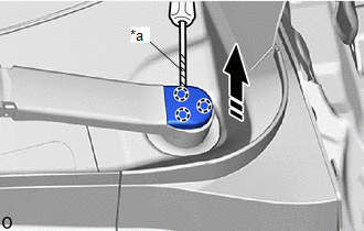
1. REMOVE FRONT WIPER ARM HEAD CAP
(a) Using a screwdriver with its tip wrapped in protective tape, disengage the claws to remove the front wiper arm head cap as shown in the illustration.
|
*a |
Protective Tape |
.png) |
Remove in this Direction |
HINT:
Use the same procedure for the RH side and LH side.
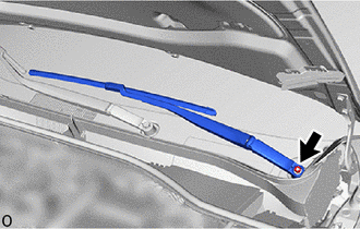
2. REMOVE FRONT WIPER ARM AND BLADE ASSEMBLY LH
|
(a) Remove the nut and front wiper arm and blade assembly LH. |
|
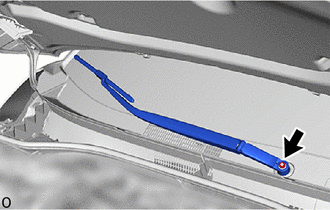
3. REMOVE FRONT WIPER ARM AND BLADE ASSEMBLY RH
|
(a) Remove the nut and front wiper arm and blade assembly RH. |
|
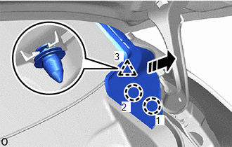
4. REMOVE WINDSHIELD OUTSIDE MOULDING LH
(a) Disengage the claws and clip to remove the windshield outside moulding LH as shown in the illustration.
|
|
Remove in this Direction |
5. REMOVE WINDSHIELD OUTSIDE MOULDING RH
HINT:
Use the same procedure as for the LH side.
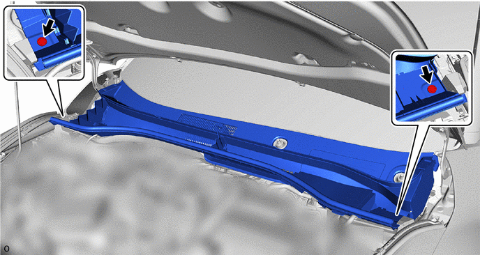
6. REMOVE COWL TOP VENTILATOR LOUVER SUB-ASSEMBLY
NOTICE:
To prevent damage to the windshield glass, remove any foreign matter (sand, dust, etc.) from around the contacting surfaces of the cowl top ventilator louver sub-assembly and windshield glass.
(a) Remove the 2 clips.
(b) Close the hood sub-assembly.
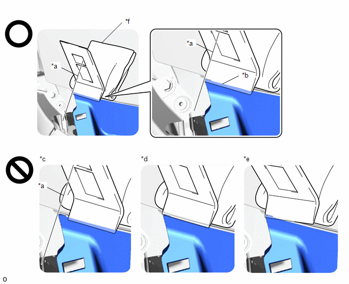
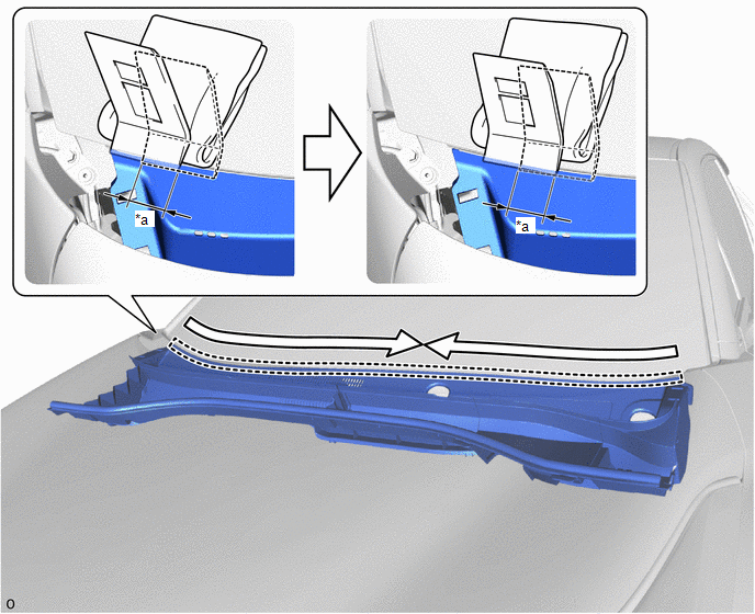
(c) Insert the moulding remover at the starting position, pushing it in as far as it will go as shown in the illustration.
|
*a |
Starting Position: Side of Cowl Top Ventilator Louver Sub-assembly and Moulding Remover Aligned |
*b |
Inserted as far as it will go |
|
*c |
Not Inserted at Starting Position |
*d |
Not fully inserted |
|
*e |
Not Inserted Straight |
*f |
Piece of Cloth or Equivalent |
NOTICE:
- To prevent damage to the windshield glass, set a piece of cloth between the moulding remover and windshield glass.
- Make sure to fully insert the moulding remover as far as it will go, otherwise the cowl top ventilator louver sub-assembly may be deformed or damaged.
HINT:
If the moulding remover is difficult to insert, slightly lift up the cowl top ventilator louver sub-assembly.
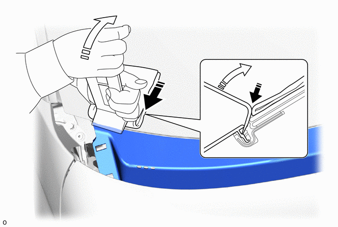
(d) While pushing the moulding remover in the direction indicated by the arrow (A), push the moulding remover in the direction indicated by the arrow (B) to disengage the cowl top ventilator louver sub-assembly.
|
|
Push in this Direction (A) |
.png) |
Push in this Direction (B) |
NOTICE:
- Make sure to repeat this procedure to disengage the entire cowl top ventilator louver sub-assembly.
- Make sure to perform this procedure while pushing the moulding remover in the direction indicated by the arrow (A), otherwise the cowl top ventilator louver sub-assembly may be deformed or damaged.
- Make sure not to pry the cowl top ventilator louver sub-assembly more
than necessary to disengage it, otherwise it may be deformed or damaged.
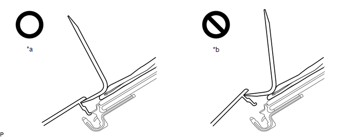
*a
Pried Until Disengaged
*b
Pried Excessively
(e) Using the moulding remover, repeatedly pry up the cowl top ventilator louver sub-assembly while gradually moving the moulding remover half of its width laterally toward the center of the vehicle and then repeat the procedure from the other side of the vehicle as shown in the illustration to disengage the cowl top ventilator louver sub-assembly from the windshield glass.
|
*a |
Half Width of Moulding Remover |
- |
- |
.png) |
Order of Removal |
- |
- |
NOTICE:
- Make sure to move the moulding remover only half of its width laterally after prying up the cowl top ventilator louver sub-assembly, otherwise the cowl top ventilator louver sub-assembly may be damaged or deformed.
- Make sure not to lift up or pull the cowl top ventilator louver sub-assembly by hand before it is completely disengaged, otherwise it may be deformed or damaged.
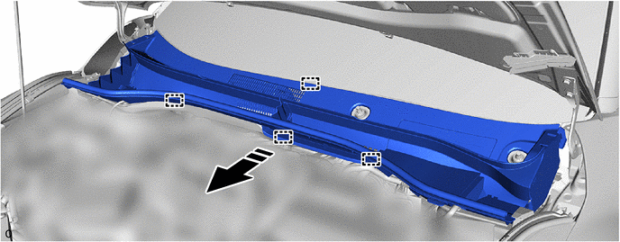
(f) Open the hood sub-assembly.
(g) Disengage the guides to remove the cowl top ventilator louver sub-assembly as shown in the illustration.
|
|
Remove in this Direction |
- |
- |
NOTICE:
When removing the cowl top ventilator louver sub-assembly, it may contact the brake master cylinder reservoir filler cap assembly and cause it to fall off. Check the installation condition of the brake master cylinder reservoir filler cap assembly after removing the cowl top ventilator louver sub-assembly.
7. REMOVE WINDSHIELD WIPER MOTOR AND LINK ASSEMBLY
(a) for USA and Canada:
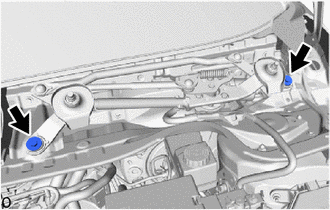
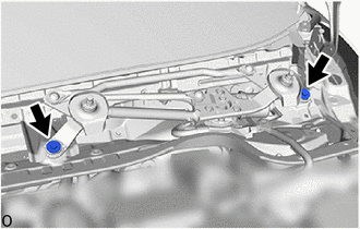
(1) Remove the 2 bolts.
|
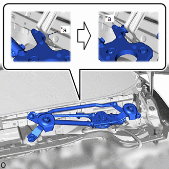
(2) Disengage the motor grommet as shown in the illustration. NOTICE: Be careful not to damage the windshield glass when removing the windshield wiper motor and link assembly. |
|
|
(3) Disconnect the connector to remove the windshield wiper motor and link assembly. |
|
(b) except USA and Canada:
|
(1) Remove the 2 bolts. |
|
|
(2) Disengage the motor grommet as shown in the illustration. NOTICE: Be careful not to damage the windshield glass when removing the windshield wiper motor and link assembly. |
|
|
(3) Disconnect the connector to remove the windshield wiper motor and link assembly. |
|
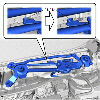
8. REMOVE FRONT WIPER CRANK SUB-ASSEMBLY (for USA and Canada)
|
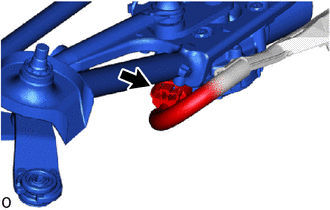
(a) Using a screwdriver with its tip wrapped in protective tape, separate the No. 1 windshield wiper link rod from the pivot of the windshield wiper motor assembly as shown in the illustration. |
|
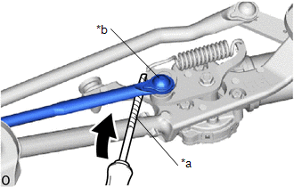
|
(b) Place matchmarks on the front wiper crank sub-assembly and windshield wiper link assembly. |
|
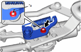
(c) Remove the nut and front wiper crank sub-assembly.
9. REMOVE WINDSHIELD WIPER MOTOR ASSEMBLY
|
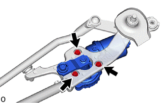
(a) for USA and Canada: (1) Remove the 3 bolts and windshield wiper motor assembly. |
|

(b) except USA and Canada:
|
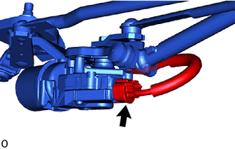
(1) Using a screwdriver with its tip wrapped inprotective tape, separate the No. 1 windshield wiper link rod from the pivot of the windshield wiper motor assembly as shown in the illustration. |
|

|
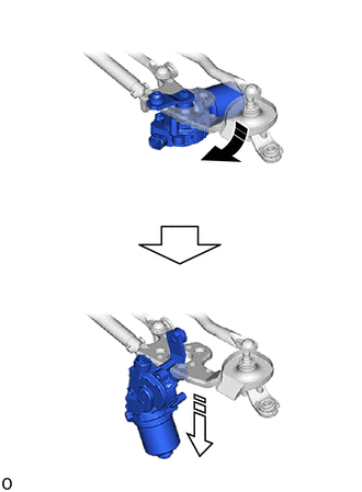
(2) Remove the 3 bolts. |
|
(3) Move the windshield wiper motor assembly in the direction indicated by the arrow (1), then pull the windshield wiper motor assembly in the direction indicated by the arrow (2) shown in the illustration to remove it from the windshield wiper link assembly.
|
|
Remove in this Direction (1) |
|
|
Remove in this Direction (2) |
 On-vehicle Inspection
ON-VEHICLE INSPECTION
PROCEDURE
1. INSPECT WINDSHIELD WIPER MOTOR ASSEMBLY
(a) for LH Side:
(1) Operate the windshield wiper motor assembly.
...
 Inspection
INSPECTION
CAUTION / NOTICE / HINT
CAUTION:
Ensure that fingers or articles of clothing do not get caught in moving parts
when performing this test.
PROCEDURE
1. INSPECT WINDSHIELD WIPER MOTOR ...
Other materials:
Toyota CH-R Service Manual > Integration Relay: Removal
REMOVAL
CAUTION / NOTICE / HINT
The necessary procedures (adjustment, calibration, initialization, or registration)
that must be performed after parts are removed and installed, or replaced during
the No. 1 integration relay removal/installation are shown below.
Necessary Procedure After Part ...
Toyota CH-R Service Manual > Audio And Visual System(for Radio And Display Type): Touch Panel Switch does not Function
CAUTION / NOTICE / HINT
NOTICE:
Depending on the parts that are replaced during vehicle inspection or
maintenance, performing initialization, registration or calibration may
be needed. Refer to Precaution for Audio and Visual System.
Click here
When replacing the ...
Toyota C-HR (AX20) 2023-2026 Owner's Manual
Toyota CH-R Owners Manual
- For safety and security
- Instrument cluster
- Operation of each component
- Driving
- Interior features
- Maintenance and care
- When trouble arises
- Vehicle specifications
- For owners
Toyota CH-R Service Manual
- Introduction
- Maintenance
- Audio / Video
- Cellular Communication
- Navigation / Multi Info Display
- Park Assist / Monitoring
- Brake (front)
- Brake (rear)
- Brake Control / Dynamic Control Systems
- Brake System (other)
- Parking Brake
- Axle And Differential
- Drive Shaft / Propeller Shaft
- K114 Cvt
- 3zr-fae Battery / Charging
- Networking
- Power Distribution
- Power Assist Systems
- Steering Column
- Steering Gear / Linkage
- Alignment / Handling Diagnosis
- Front Suspension
- Rear Suspension
- Tire / Wheel
- Tire Pressure Monitoring
- Door / Hatch
- Exterior Panels / Trim
- Horn
- Lighting (ext)
- Mirror (ext)
- Window / Glass
- Wiper / Washer
- Door Lock
- Heating / Air Conditioning
- Interior Panels / Trim
- Lighting (int)
- Meter / Gauge / Display
- Mirror (int)
- Power Outlets (int)
- Pre-collision
- Seat
- Seat Belt
- Supplemental Restraint Systems
- Theft Deterrent / Keyless Entry

0.0083